Weekly Question:
This week, the knowledge that I learned in the following classes aided my design process:
18320, 18623, and TAing 18100: These classes helped me understand the design considerations and techniques when building analog circuits. For 18320 and 18623 has helped me develop skills in hand calculating circuit performance, and 18100 TAing has given me experience in actually building circuits and making them robust. This was relevant primarily for designing the strum detection circuitry, which handles analog signal processing.
18240, 18320: These classes helped me understand the timing requirements and considerations when creating circuits with flip-flops, which we used in the design of the fretboard PCBs. This allowed me to understand the data given on datasheets for flip-flops, enabling me to be confident in the choice of flip-flop I made.
I don’t have any formal coursework in PCB design. However, for past personal projects and internships I have done PCB design. My experience in the past was with Altium and EasyEDA, but for this project I decided to use KiCAD. This was mainly done since KiCAD has become a very popular tool recently and I wanted to switch away from EasyEDA. I was mainly able to use my experience from previous design software to figure out how to use KiCAD, but I also found posts on KiCAD forums useful when learning application-specific keybinds and shortcuts.
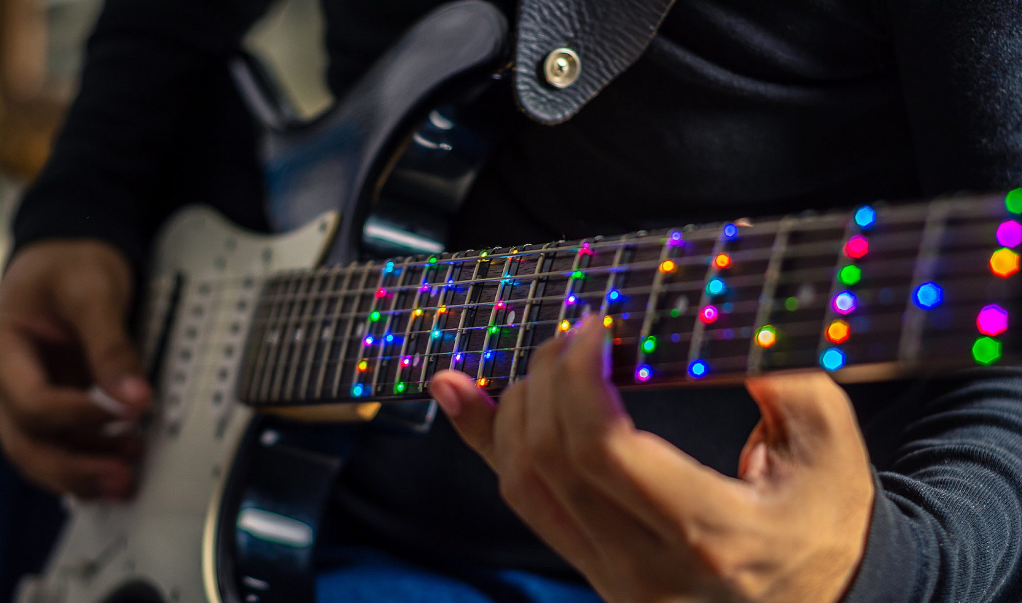
This week, I finished the design for the fretboard PCBs and put in an order for the boards and the parts. The main changes to the design were the layout of the I/O pins, adjusting the spacing of the LEDs to match the guitar we are ordering, and adding a ground plane. The pinout was changed to make the PCBs easier to chain together without overlapping wires.


In addition to updating the PCB and ordering the parts, I also continued working on the detection of strumming in hardware. I have a design that currently functions on a breadboard but needs fine tuning. This will likely wait until next week when we have the physical guitar, as the tuning of values should be done for that system. The general processing done to the audio signal is shown below.


I have also begun the initial design process for the PCB that will house the microcontroller, strum detection circuit, buzzer for the metronome, logic level conversion for the LEDs, and power distribution. My current thoughts are to make a hat for the RPi. This will have the Teensy, a barrel jack for power, an active buzzer, and a handful of headers/pads to connect to the LEDs, fret sensors, and microphone.
I am currently on schedule. For next week I hope to test the strum detection circuit on the actual guitar. This will allow me to fine-tune the component values used for the circuit and ensure that the system will work. We have a fall-back plan of using the piezoelectric pickup that is built into the guitar. We can tap into this signal (or the amplified version) for likely a much higher signal-to-noise ratio signal compared to the microphone. I would also like to begin planning the general layout of the PCB, such as creating the general outline for the hat and the pin headers to attach the PCB to the Pi. If the fretboard PCBs come in, I also aim to begin assembly of the boards so testing can begin soon.
