This week, we started the integration of all the different systems. We switched to using fiducials on the robot because we could not account accurately for the differences in the ambient lighting causing the web camera to auto-correct in the color quantization. The most significant risk is that we need to figure out why the controller is not able to get the robot to follow a path. It could be the PID tuning or the small turning radius desired by the path planner. We are confident that we will be able to make the robot follow a path correctly.
Omkar’s Status Report for 10/29
This week the entire team met and worked on the integration between computer vision, path planning, and controls. We were able to command robots based on the trajectory, but we ran into issues with the different coordinate systems that the computer vision and controls used. We fixed those problems, but our controls code worked in simulation and not when we tried with real robots. The issue seems to be how the PID values are tuned, and trying to find a balance between driving too slow or too fast. We seem to be on track by our Gantt chart. By next week, we want to be able to have a robot follow a path as closely as possible and implement pallet pickup and dropoff.
Prithu’s Status Report for 10/29
This past week, most of my work was around the integration of the motion planner into the rest of the system. Since the motion planner was written in C++ for efficiency I had to use the Pybind11 library to allow Python to call the planner functions. The entire team also met this week to work on integrating all parts of the system together (CV, controller, planner) and were able to get the robot moving. We had some issues with the controller and planner related to path following and turn radius constraints that we are going to work on fixing when we meet again tomorrow.
Saral’s Status Report 10/29
This week I spent a lot of time on robustifying the computer vision algorithm to perform well in various lighting conditions and with blocked LEDs used for localization. In parallel I brought up a fiducial based robot localization system that seems to be far more reliable than the LED based approach. Since we have 2 working approaches, we might be able to perform some sort of sensor fusion on them too.
Additionally, we met as a team to perform integration and managed to sort a lot of bugs in the interface between the computer vision and the rest of the robot system.
Omkar’s Status Report for 10/22
Since the last status update, I have worked primarily on the design report. I also refactored the controls software on the main computer with a better interpolation between the waypoints (matching the design report). The interpolation is to compute the feedforward term for our controller as well as for the target pose for the robot for the feedback term. Previously I did the interpolation as a cubic spline between the waypoints, enforcing the orientation at each of the waypoints, but this did not account very well for when the robot stayed in place for a period of time. This led to a refactoring of the controls code to compute the trajectory between waypoints in real time rather than precomputing the trajectory when the controller is initialized.
Saral’s Status Update 10/22
This week, I worked on robust-ifying the Computer vision LED-Robot detection.
As a quick recap, the way the computer vision localization works is that the program applies an image mask to the image captured to isolate the LEDs from the appropriate robot. After this, the algorithm does the inverse affine transform, scaling etc.
However, due to manufacturing inaccuracies in our LEDs, changing ambient lighting conditions, camera inaccuracies, off-axis image shift etc, using a hardcoded LUT for which robot color is which is simply not robust and has been giving us a lot of issues.
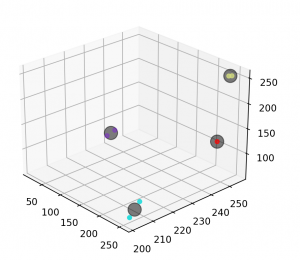
As such, I refactored the computer vision algorithms to use K-nearest-neighbors to run an unsupervised clustering classification algorithm at runtime to figure out which LED is which. This adds practically no extra latency/compute overhead during runtime since all the algorithm does is a distance calculation to the centroids of each of the clusters.
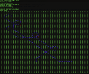
Included below is a visualization of 4 robot colors (Orange, 2 types of blue, Green) and also subsequently the clustering centroids and the detected pixels. As you can see, often 2 types of LEDs with the same color have enough noise/discrepancy in the detection that the clustering approach is definitely the right approach to this problem.
Prithu’s Status Report for 10/21
This past week (before fall break) I was away in New York to attend an event with CMU Leadership. Most of my time was dedicated to writing portions of the Design Report. Specifically, I focused on sections related to the motion planner and the use-case/design requirements. I know there were some concerns regarding the clarity of our explanation of the planning algorithms so my top priority was to have the information presented in an easy-to-understand in-depth way. In addition to working on this document, I also started the process of integrating the planner (C++) with the rest of the codebase (Python) using a library called Pybind11 which allows you to call C++ functions from Python.
Team Status Report for 10/8
This week, our team split off and worked on the various parts of the software for the robots. Saral worked on the CV bring-up: specifically the localizer for the robots and pallets. He was able to get the fiducial recognition working so that we can differentiate between pallet types. Omkar worked on getting the feedforward and feedback controller for the robot working so that it can follow a path given positions and timesteps. Prithu worked on the motion and task planner which takes in the robot, pallet, and goal positions, and returns position/time paths for the robots to follow.
We plan on meeting Monday to integrate the code together and run a test of the full system.
Prithu’s Status Report for 10/8
This past week, my main focus was writing the robot’s task and motion planner. The current version of the algorithm works by assigning priorities to each robot and then precomputing the paths for all the robots so that they don’t collide. This works by planning in (x, y, theta, time). The map was discretized into a 2D grid where each box is 1cm x 1cm. This resolution can be changed as needed based on the planning time. The planner also takes into account the physical constraints of the robot (collision footprint, turn-radius constraints). Here is a picture of the result of planning for two robots. Paths to the pallet and from the pallet to the drop-off zone are planned at the same time.
Saral’s Status report for 10/8
This week I focused on a refactor of the Computer Vision Localizer to bring it from a ‘demo’ state to a clean implementation as outlined by our interface document. This involved redoing the entire code structure, removing a lot of hard-coded variables and exposing the right functions to the rest of the application.
I also worked on creating 8 distinct images for the robots to display and calibrating them for the algorithm via a LUT to account for the errors in the camera and neopixel’s not being perfectly color accurate.
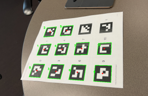
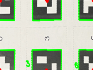
I also worked on making the Computer vision code work with the fiducials. The fiducials are the QR code pieces that allow a human to place them at the edges of a sandbox (table). Based on the fiducial locations, I was able to write an algorithm to detect what fiducials were in what order and appropriately apply a homography to the sandbox and scale it such that each pixel was 1mm wide. This allows us to place the camera anywhere, at any angle and get a consistent transformation of the field for localization, path planning, and error controller! It also allows us to detect the pallets.
Attached below is an example. Pic 1 is a sample view from a camera (the fiducials will be cut out in reality) and Pic 2 is a transformation and scaling of the image between the fiducials [1,7,0,6] as the corner points