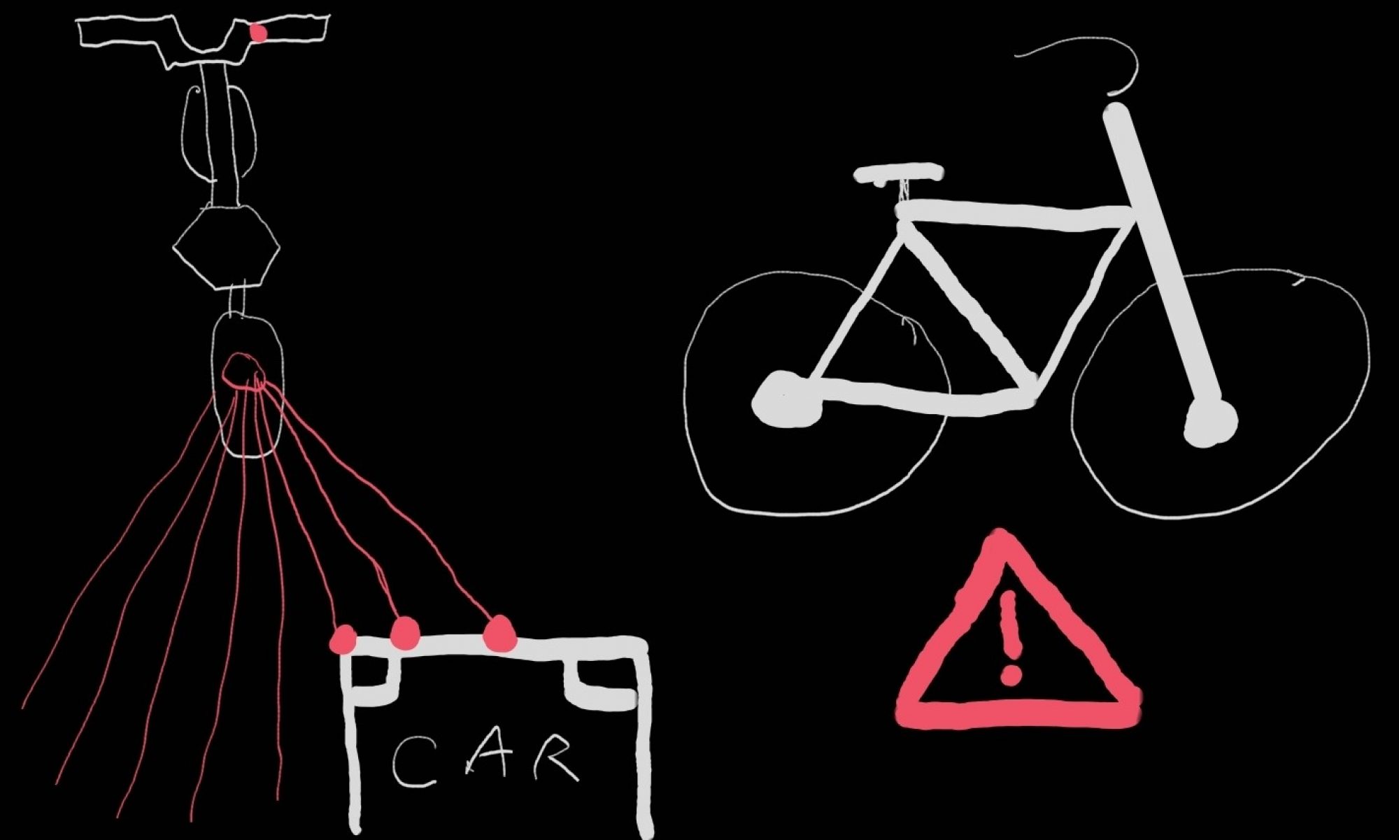

Emily and I were going to test the entire setup, but upon arriving noticed some issues with STM arduino communication so I have spent this week debugging with the group. When testing the STM I noticed the waveforms were not reaching adequate triggering level for the arduino, Jason was able to fix this the next time he came in. The two heat-wrapped LED connections failed and so were redone with the addition of hot glue. The communication cable for the arduino and STM was accidentally severed and also redone. I also soldered connections for the turn signaling switch. Jason and I at the end of today were able to get the singals code showing on LEDs and will now work on refining the values in that code for real life.
Final Presentation Slides
Presentation Slides: Team_B3_Bloor_Clayton_Xu_Final_Presentation
Team Status Update 20 NOV 2021
This week as a team we completed separate stationary testing of the two sensors and determined our achievable range to be around 10m. Though below our specifications, we have passed our abort date and thus will see the project through with this sensor (an email has been sent to manufacturer to determine if some un-thought-of issue could be the cause). We have been trying to document our testing process with a few photos and plan to test the sensors on mount on 21 NOV. Code integration for the Signals Processing code and driver interface went fairly smoothly thanks to good communication beforehand about expectations. However, some issues have arisen in communication between the STM and Arduino. The two run at different high logic levels (3.3V and 5V) and though a pull-up resistor was attempted, we are still in the process of setting up the necessary communication channel. As we are not using all the pins on both devices, a backup plan of using direct control between 6 ports on each is possible if the serial communication continues to present issues. New battery have been received to get around some issues that we were encountering with buck converters, and the mount is going to be sent for re-print as some minor changes have been made. The old mount may still be used for testing as the changes do not effect the positioning of the sensors.
Albany’s Status Update 20 NOV 2021
This week, I did try to measure the current draw from one of the sensor’s when hooked up to the Arduino to see if this was a possible cause of the smaller than expected range, but was unable to get the multimeter working properly in the series current measure configuration. However, when hooked up to a 5V power supply, the current draw was under what would be possible for the Arduino. Emily and I got together to test the second sensor in the same manner as the first.
We received roughly the same results as with the first sensor. The range extended to about 11m. Interesting, accurate distance information was still returned after the car fell of the spectral line array, though only for about half a meter. As it was raining, this also allowed us to confirm that the operation of the sensor was not effected by precipitation (assuming the two sensors have the same clear weather range), though this was never expected to be a problem. We discussed trying to test the beamwidth of the sensor, but determined that though we were able to hold the sensor a certain distance away with insignificant error (1 or 2 cm over 1 or more meters) that even with a compass to determine angle, we could not hold the sensor at the correct angle. This testing will be preformed once the sensors are more securely on the mounts. Emily and I currently have plans to get together 21 NOV to preform mounted sensor testing with both sensors.
I also talked to Jason this week and took him through the interface for my code so that it could be integrated easily. I believe he now understands how to call the written functions on the data collected by the sensors. I also took some time to solder a few components for connections. I added the photoresistor to a circuit board with resistor and wiring for Emily so that she could use said setup to determine whether taillights would need to be on. I also started soldering some wires to male-to-male connector pins we are planning to use with the STM as they are still removable if necessary, but fit much more securely than wire alone.
Albany’s Status Update 13 NOV 2021
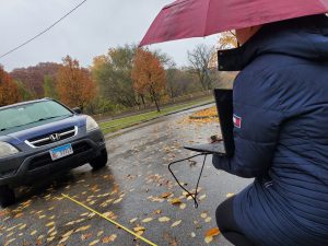
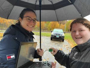
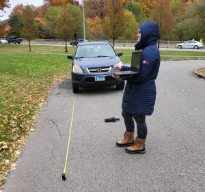
Following up on last week, Emily and I did agree to use the communication format mentioned in my last status report to communicate between the LEDs and the SP code and a function to handle this transformation and combine data from two sensors was implemented. It also turned out that the data collected from the top of the East Campus garage was very hard to analyze, I believe largely due to the fact that a metal guard rail was running next to us during the entire time of testing. To get a new data set, Emily and I took some stationary measurements in a turnaround in Schenley Park (see picture).
This data was clearer, but worrying, and a simplified summary can be seen in the following chart.
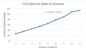
The y = 11.35x + 11.917 equation gives a to predict the location (index) in the spectral line data in which the first peak occurs at x meters from the car. This is worrying for two reasons. The manufacture specifications indicate that a peak one spectral line index later should be 0.126m further away which would correspond to a slope above of about 8. The slope of 11.35 means that the distance between each spectral line index is only 0.088m. With 126 spectral lines this would mean we would only expect our maximum range to be 11.1 meters, but the relatively high y intercept when means that for y = 126, we really only see a max range of 10m. We plan to, in the lab on money, use a multimeter to measure the current being pulled by the sensor from the arduino to see if we are providing enough power. I would also note that all measured testing thus far has been done with one of the sensors, so it might make sense to see if this range problem exists with the second sensor as well. Theoretically, from the manufacturer, we should be able to get a range of about 20m. It is possible that the y intercept problem is introduced by us measuring from the license plate of the car while the larger metal engine block is slightly recessed, though this wouldn’t affect slope. All of the above calculations are made using the spectral lines since they are necessary for multiple object detection and are what our code uses, but I also plan to look at the 16bit distance data, though a cursory look does not seem to present an any more promising story. I am also curious, the Emily and I stopped recording data once it fell off the spectral lines, if the distance data would track for the latter half of the 20m.
Team Status Update 6 November
We started the week as a team by making sure that having two sensor running next to each other would not create interference by running a quick test of them on Frew street though without particular measurements as it was just for proof of concept. We have gotten some data back for single data testing in measured conditions, but the metal railing of the parking garage seems to have created a fair amount of interference so it is hard to isolate the data from the car alone. Between Emily and Albany the LEDs have been soldered together and tested to make sure they were controllable and I believe the driver for STM is also close to being stood up. Further we have most of our 3D printed mount parts to start assembling everything into a more compact format once, though it was discovered that we would need to make an extension for the LED signaling lights as the was erroneously excluded from the print plans.
Albany’s Status Update 6 NOV 2021
This week I removed the memory management from the signals processing code and changed the functions so they used passed in arrays that could be stored on the stack to prepare the code for integration. Theoretically code integration should have happened last week, but we did have an extra integration week and refinement week built into the schedule before Thanksgiving to allow for some flexibility. I also took one of our sensors to the roof of the East Campus parking garage and recorded data from it from a selection of distances while stationary and also while walking towards and away from the target car. Finally, I also spent a couple hours in the lab learning how difficult it is to solder very small LED contacts to connection wires. Things sped up significantly after I found some better solder, and I ended up making the two side rear groupings of three LED strips each. I also hotglued over the connections for those grouping and for the handlebar and brake light strip Emily soldered to protect the connections and provide support given the small contacts. Next week I plan to discuss with Emily my current plan for passing information to the handlebar LED controller. I’ve been told we have 7 bits to control the 3 sections we have with 4 states each so each section could be controlled by two bits, leaving to possibly be flipped to indicate a new object and flash the bar. I believe Jason is also ready to integrate the signals processing code so I want to walk through the simplified version of it that currently exists with him and make sure we have remained on the same page for the interface between our code and that something hasn’t been lost in translation.
Albany’s Status Update 30 OCT 2021
After more extensive talks about how to handle memory for the signals code that is being placed on the STM23, I was advised that for integration purposes, that code hosted on the processor should allocate memory directly onto the stack as opposed to using malloc to allocate memory onto the heap, so I am currently in the process of making the necessary changes to make this switch. I am unsure whether the current memory handling structure will be kept as I am looking into possibly simplifying certain aspects of it as initial testing with the microwave sensors seems to suggest that there will be no need for code to cancel out any noise created by the ground. Prior to starting these changes, this week I finished debugging the code for determining velocity (the main issue was that I had used one convention for the positive direction early in the code and then seemed to accidently reverse the convention in determining what to display to the user). I currently have the code returning distance over velocity (i.e. extrapolated time until impact if current velocity maintained). The code is correct for the limited number of cases I was testing on, and after completing the memory switch my next step will be to retest this correctness with a larger number of test cases and with some real-world data that we can now extract from the sensors. The current code is the processing code for a single sensor and I either in the coming week or the one after that depending on what occurs in the next round of correctness testing also need to make sure my teammates and I have a good idea of how to take the results from the two sensors and transfer this information to the LED display. The single sensor processing code already filters to return distance over velocity only for objects of interest. I envision then that this LED code will determine first which object are seen by both sensors and select them to determine display for the center segment (though distance info might also be needed for this to ensure an object two times the distance going twice the speed of another doesn’t appear to be the same) of LEDs, then the lowest distance over velocity for each segment should be used to determine color. We are slightly behind schedule, but we had a couple weeks of padding built in that give us some leeway. Our current adjusted aim is to integrate everything the week after next, so I hope to have the code usable by then.
Albany’s Status Update 23 OCT 2021
This week I did some debugging on the code and ran it through some simple tests. The code compiles and there are no memory leaks according to Valgrind, but after talking with Jason, it seems that how we manage memory might change when we actually move the code onto the board. For now though, this means all the list management and freeing seems to be problem free. Since memory management is going to change, I didn’t run any timing tests, but checked correctness for the distance calculations which seem to working for all the arrays I was running through it. I am having some problems with the speed difference function, I think its arising from trying to filter out objects that enter frame from the front as though it were being passed. I’ve heard Jason has gotten the Arduino and microwave communication up, so I hope to be able to have some data examples soon to be able to move on with the filtering code for ground, or to see if there are any unexpected features of the returned data.
Team Status Update 23 OCT 2021
As a team this week as part of the ethics assignment we put a bit of thought into any ethical issues with our project and got to hear from the rest of the class. The largest problem we found was overreliance on the sensors and accountability if they should fail. We also took some time to measure out the bike we’re mounting the prototype to together and briefly looked over the code.
Last week we finalized purchases for most of our equipment and finally got the sensor in which I believe we should have data back from soon. We also had some discussions about what objects to filter in showing to the rider and how to display different hazard levels, currently landing on colored LEDs.