
Presentation Slides: Team_B3_Bloor_Clayton_Xu_Final_Presentation
Team Status Update 20 NOV 2021
This week as a team we completed separate stationary testing of the two sensors and determined our achievable range to be around 10m. Though below our specifications, we have passed our abort date and thus will see the project through with this sensor (an email has been sent to manufacturer to determine if some un-thought-of issue could be the cause). We have been trying to document our testing process with a few photos and plan to test the sensors on mount on 21 NOV. Code integration for the Signals Processing code and driver interface went fairly smoothly thanks to good communication beforehand about expectations. However, some issues have arisen in communication between the STM and Arduino. The two run at different high logic levels (3.3V and 5V) and though a pull-up resistor was attempted, we are still in the process of setting up the necessary communication channel. As we are not using all the pins on both devices, a backup plan of using direct control between 6 ports on each is possible if the serial communication continues to present issues. New battery have been received to get around some issues that we were encountering with buck converters, and the mount is going to be sent for re-print as some minor changes have been made. The old mount may still be used for testing as the changes do not effect the positioning of the sensors.
Albany’s Status Update 20 NOV 2021
This week, I did try to measure the current draw from one of the sensor’s when hooked up to the Arduino to see if this was a possible cause of the smaller than expected range, but was unable to get the multimeter working properly in the series current measure configuration. However, when hooked up to a 5V power supply, the current draw was under what would be possible for the Arduino. Emily and I got together to test the second sensor in the same manner as the first.
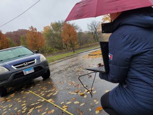
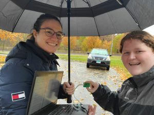
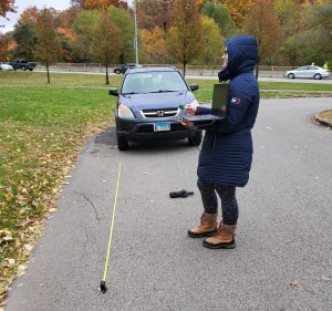
We received roughly the same results as with the first sensor. The range extended to about 11m. Interesting, accurate distance information was still returned after the car fell of the spectral line array, though only for about half a meter. As it was raining, this also allowed us to confirm that the operation of the sensor was not effected by precipitation (assuming the two sensors have the same clear weather range), though this was never expected to be a problem. We discussed trying to test the beamwidth of the sensor, but determined that though we were able to hold the sensor a certain distance away with insignificant error (1 or 2 cm over 1 or more meters) that even with a compass to determine angle, we could not hold the sensor at the correct angle. This testing will be preformed once the sensors are more securely on the mounts. Emily and I currently have plans to get together 21 NOV to preform mounted sensor testing with both sensors.
I also talked to Jason this week and took him through the interface for my code so that it could be integrated easily. I believe he now understands how to call the written functions on the data collected by the sensors. I also took some time to solder a few components for connections. I added the photoresistor to a circuit board with resistor and wiring for Emily so that she could use said setup to determine whether taillights would need to be on. I also started soldering some wires to male-to-male connector pins we are planning to use with the STM as they are still removable if necessary, but fit much more securely than wire alone.
Emily’s Status Update
We’ve switched to using 5V batteries which we got in this week. I didn’t realize that the Arduino can run off of 5V through the 5V or through the USB input. This will also double our battery capacity. I tested them, they run at the required voltage. I’ve gotten the LEDs and the Arduino to run off of the battery power. I still have to test the STM, but it worked with the 12V, so this should be alright as well. Next up with power is to run the sensors off of the STM.
Jason and I tried to get various communications methods working between the STM and the Arduino. I’ll be helping with that more actively next week.
I’ve started modifying the CAD for the final version of the mount. We changed how the batteries are going to be positioned relative to the bike, so the mount overall will be smaller now and I won’t have to print it in two pieces. I’m also planning on printing circular clips to hold the turn and power switches on the bike.
I also got our light sensing to work on the Arduino. We use it to inform whether the tail lights need to be on, and I’m going to change it to set the overall brightness for the handlebar LEDs as well (so they aren’t so blindly bright at night).
I did some testing with Albany on the other sensor a couple days ago, and we are going to meet up on Sunday to do testing with the two sensors together on the mount. We are also going to use this to test the angular response of the sensors.
I emailed DFRobot about the sensors. We aren’t seeing the range that we expect and their documentation is very limited and unclear, so hopefully they will get back to us soon. We are continuing to move ahead, but it would be nice to get some kind of answer to what we are seeing.
Jason’s Status Update 11/20/2021
This week, I worked on integrating the code from Albany into the STM32 library, and trying to interface with Emily’s LED code by sending LED codes to the LED arduino.
Code integration worked well, as the requirements were communicated well and ahead of time, and Albany left a clean interface to device memory for me to implement. However, interfacing with the Arduino proved much more difficult than usual. My initial idea was to use I2C, but through hours of debugging, including trying different pull-up resistor resistances and using the oscilloscope to debug, I still haven’t been able to get it working. SPI also fails to display any message on the oscilloscope.
My next plan is to work with Emily to interface directly with the STM32 registers without the hardware abstraction library (HAL) that some say is problematic, and if that fails I will fall back onto the inelegant but effective solution of using 6 separate digital pins to output the LED codes directly through GPIO. Before this is done, however, I am able to get the LED codes to output through USB serial, so debugging and optimizing Albany’s code can continue.
Team Status Update 11/13/2021
This week before class time, our team prepared for the interrim demo by finalizing the work we’ve done separately and present them in a working form. This includes the LED circuitry worked on by Emily, the data collection and signal processing by Albany, and the software interface with sensors by Jason. Overall the demo went well, with no major problems.
After the demo, Emily and Albany went to Schenley park to take some measurements with the sensor as part of the next round of testing, with the goal of getting more detailed data. The results showed us that the specs given by the manufacturer of the microwave sensor were not correct, as we were only able to get about 10m of usable range, which we will investigate this week.
Progress has also been made to the power circuitry, enabling the lights and the microprocessors to be run off battery, and the software, fixing a problem with data alignment and enabling the I2C master bus to communicate with the LEDs. We will work to start integrating the components next week, and iron out any bugs that appear in the process.
Emily’s Status Update 11/13/21
Changed the LED code so that the different zones update concurrently. Before, each LED set would update in a serial fashion, but now they all update at once. Did some testing yesterday with Albany and my car and the sensors in an empty space so that we could get some data with less interference.
Been working on the power stuff. The Arduino and the STM can now run off the battery power. I just need to select the proper inductor size for the LEDs, and those will be ready to go as well. I’m thinking of switching the microwave sensors to run off of 5V rather than 8V because it seems unnecessary to have specifically 8V for it when it can run off of 4-8V. However, some of the data that we got from the sensors seem to suggest that the output range might be proportional to voltage and not power, so that would be a problem. I’m going to do some testing on Monday to make sure that this isn’t the case before switching over to only 5V converters.
Jason’s Status Update Nov. 13
This week, we successfully demoed the components of our project separately as part of the interim demo. To prepare for this, I expanded the STM32 code to read both microwave sensors through separate UART busses, adding alignment to data headers so that the sensor data would be in the correct locations of the buffer.
Unfortunately some problems arose during the demo, in which the Python program printing out data received by the STM32 was coalesced, and was shorter than what was expected. I investigated this error through the STM32 debugger and concluded that the problem stemmed from the timing of the Python program itself, since the internal data arrays were all aligned correctly without problem.
I also did some basic profiling and benchmarking to assess the feasibility of the STM32 that we chose, and concluded that the UART reads, although slower than what we expect, exceeds our user requirement for 250ms update time (4Hz). I also found out that the time difference between two reads is negligible for our use case, and that one spectral data array occupies less than 1% of the device memory. According to Albany’s code, I have verified that the STM32 is indeed capable of running our workload well.
In the next week, I plan to start integrating the code from Emily and Albany. First I plan to write a test program to control the LEDs using the 7-bit LED codes that we agreed on, and then a ring buffer for storing data necessary for Albany’s signals code. After that, I will integrate that with the signal processing routine that Albany has written and start testing.
Albany’s Status Update 13 NOV 2021
Following up on last week, Emily and I did agree to use the communication format mentioned in my last status report to communicate between the LEDs and the SP code and a function to handle this transformation and combine data from two sensors was implemented. It also turned out that the data collected from the top of the East Campus garage was very hard to analyze, I believe largely due to the fact that a metal guard rail was running next to us during the entire time of testing. To get a new data set, Emily and I took some stationary measurements in a turnaround in Schenley Park (see picture).
This data was clearer, but worrying, and a simplified summary can be seen in the following chart.
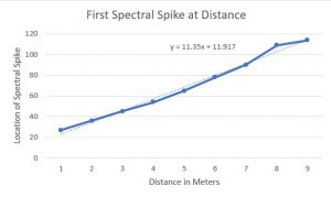
The y = 11.35x + 11.917 equation gives a to predict the location (index) in the spectral line data in which the first peak occurs at x meters from the car. This is worrying for two reasons. The manufacture specifications indicate that a peak one spectral line index later should be 0.126m further away which would correspond to a slope above of about 8. The slope of 11.35 means that the distance between each spectral line index is only 0.088m. With 126 spectral lines this would mean we would only expect our maximum range to be 11.1 meters, but the relatively high y intercept when means that for y = 126, we really only see a max range of 10m. We plan to, in the lab on money, use a multimeter to measure the current being pulled by the sensor from the arduino to see if we are providing enough power. I would also note that all measured testing thus far has been done with one of the sensors, so it might make sense to see if this range problem exists with the second sensor as well. Theoretically, from the manufacturer, we should be able to get a range of about 20m. It is possible that the y intercept problem is introduced by us measuring from the license plate of the car while the larger metal engine block is slightly recessed, though this wouldn’t affect slope. All of the above calculations are made using the spectral lines since they are necessary for multiple object detection and are what our code uses, but I also plan to look at the 16bit distance data, though a cursory look does not seem to present an any more promising story. I am also curious, the Emily and I stopped recording data once it fell off the spectral lines, if the distance data would track for the latter half of the 20m.
Jason’s Status Update Nov. 6
This week, I focused on getting the sensors to work with the STM. So far, I have initialized both of the microwave sensors and written interrupt handlers to write data into a shared buffer. I have also verified that it is working by reading from the STM from the Python terminal. Finally, on the STM, I initialized the I2C ports to communicate with the LED controller in the future. For the demo, I will be preparing a demo with Python to showcase the reading of microwave sensors on the STM, after which we are ready to start integrating. I also taught Albany how to use my Python code to read the microwave sensor on an Arduino, which she will be using to test the sensors on the weekend.
I have run into an issue by discovering that neither the Arduino nor the STM32 has an accelerometer, which Albany will need for signals code, but thankfully I had one on hand from Build18 last year. It provides 9 degrees of freedom, which is much more than we need. I will start integrating it next week, while providing Albany with the format of data it provides.