Ryan’s Status Report for 12/5/2020

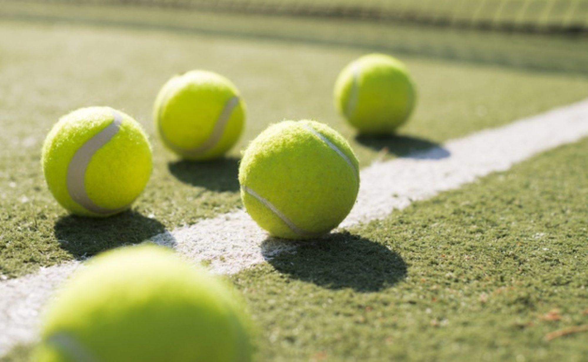
With the robot’s construction finalized, we focused on final touches and testing this week. We stared with our final integration test. This test would ensure that the addition of a basket didn’t adversely affect any other components of BallBot. To perform this test, we set up a testing environment in the capstone lab and sent BallBot through it. Below is a video of the result:

As one can see, the addition of the basket did not seem to negatively impact any of the existing systems. BallBot was successfully able to pick up all the tennis balls.

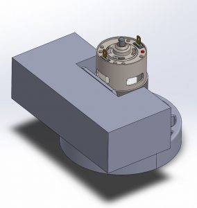
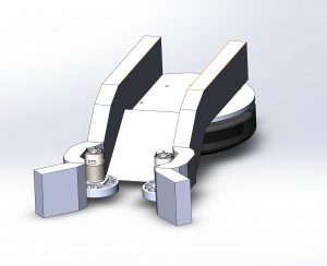
After verifying that our system fully integrates, we decided to remodel the top of the robot to incorporate a touchscreen displaying our user interface. In Solidworks, I revised the design to include another layer on top of our sensor suite to house the screen. The final CAD model of BallBot is shown below:

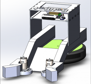
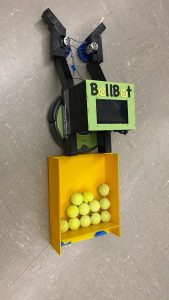
With the model finished, I cut the new layers out of acrylic and assembled + painted them in the lab. We attached the touch screen and hooked up the Nvidia Jetson Nano. At this point, the final physical construction of BallBot was complete. A picture of BallBot in its final form is shown below:

And here’s a video of the new and improved BallBot running through the same test from earlier:

BallBot was able to successfully pick up all but one of the tennis balls. Failure to scoop up the last tennis ball was due to a software bug, which has since been fixed.

For next week, I plan on working on the final presentation and video.

Ryan’s Status Report for 11/21

This week was midterms week for me, so I was not able to work on our capstone project during the middle of the week. I was, however, able to work some on the project at the beginning and end of the week.

With the mechanical portion of BallBot nearly complete, I started the week by experimenting with a slight modification to our current ball launching mechanism. The goal of this experiment was to determine if angleing the wheels would help launch the balls higher. The higher we can raise the ball, the more balls we can store in our basket towards the back of BallBot. Below are some results from my experiments:

As one can see, angleing the motors lifts the balls off the ground, even in the absence of a ramp.

Towards the end of the week, I worked with the team to attach our basket to the back of BallBot. We wanted the basket to be easily removable, so we settled on a hook design. This design is much like how one would hang a painting on the wall. Below is a picture of the attaching mechanism:

With the basket locked in place, we are ready to do a full integration test on a tennis court. Unfortunately, the Pittsburgh’s weather is not looking great next week, so we’ll have to cross our fingers and take the first opportunity we get.

Ryan’s Status Report for 11/14/2020

This week I focused on finishing up the mechanical work and integration testing. For the mechanical side, I designed a top layer platform to house the battery, Jetson Nano, buck converter, camera, and additional circuitry. The updated BallBot CAD model is shown below:

After verifying the designs, I quickly constructed the top layer from acrylic, and attached all the electronic components using M3 Dual Lock adhesive. We chose this adhesive because it, like velcro, allows us to quickly remove and service parts, but it has better durability than velcro. Below is the arrangement of our electronics on top of BallBot as well as a front view of BallBot.

With all the sensors and compute attached to BallBot, we could switch our focus to integration testing. We loaded our most recent code onto the onboard Jetson Nano, set up a chain of balls in the lab, and let BallBot run. Here is a video of the result:

As demonstrated above, BallBot is able to autonomously drive towards and pick up tennis balls.

To end the week, we decided to give BallBot a makeover. We painted the bot black with our logo in green. Below is a picture of the new BallBot:

For next week, I plan on finishing the mechanical construction by building the basket attachment. Additionally, we plan on doing our final integration tests on the CMU tennis courts.

Ryan’s Status Update for 11/7/2020

This week was a very productive week the mechanical side of Ballbot. I began this week by attaching a ramp between the two railings assembled last week. Below is a picture of the assembled ramp and runway ontop of the iRobot Create 2.

Before I continued with the assembly, I wanted to verify that the ramp was capable of raising tennis balls from the ground to the top of the iRobot Create 2. I rolled some tennis balls towards the ramp and observed the following:

As one can see, the ramp deflects tennis balls straight upwards instead of the up and towards the back of the robot as desired. This suggests that the ramp is too steep, so I went back to the designs and decreased the ramp’s angle from 45 degrees to 30 degrees.

With this new design, I recut and reassembled the ramp. After some additional testing, I was confident that the new ramp could deflect tennis balls towards the back of the robot, so I continued with the assembly. I attached the motor mounts to the railings and added our motor assembly. Now I was ready to test our tennis ball launching mechanism. Below are two videos of the mechanism in action:

After testing our launching mechanism, I added the arms and caster wheels to the motor mounts to complete the robot frame assembly.

For the rest of the week, I focused on developing a method for attaching the assembled frame to the iRobot Create 2. After some initial difficulties, I decided to screw together the Create 2 top plate, our acrylic top plate, and the wooden runway railings with six screws. The screws used to fasten the frame to the Create 2 are shown in the following video:

Using this method, we joined the frame to the iRobot Create 2 to complete the front side of Ballbot pictured below:

To end the week, I ran a mechanical integration test to see if the robot was able to pickup tennis balls when being controlled manually. Although we do not have a basket yet, Ballbot was to pick up all the balls and “shoot” them out its back. Take a look:

With the front side of Ballbot finished, we’re in a pretty good position for our demo next week. For next week, I plan on adding a roof (to help guide the tennis balls) and second layer to Ballbot (to house our battery, Jetson Nano, and camera). If I have time, I’ll begin prototyping our tennis ball basket.


Ryan’s Status Update for 10/31/2020

With the simplified designs from last week, I was able to make significant progress this week on the construction of robot frame.  During the week, I was able to use the wood working tools in the makerspace to cut 2×3 wood planks into the necessary shapes for construction. After making all the cuts, I began the assembly of the frame. In the past, we made the mistake of using screws to join two pieces of wood. This proved to be very challenging, so this time we decided to switch to using glue. We thought glue would be a better choice since its easy to apply has a relatively strong bond. Below are pictures of the assembled motor mounts and railings.

Below are some pictures of the mostly assembled robot frame. We still have to attach the robot’s arms to the left of the motor mounts.

For next week, I plan on completing the robot frame and starting work on the acrylic pieces needed to attach the frame to the robot. To cut the acrylic, I’ll use the makerspace laser cutters, and I’ll use 4mm screws to attach the acrylic pieces to the wooden frame and iRobot create 2.

Ryan’s Status Update for 10/24/2020

This week was rather busy with midterms, but nonetheless, I was able to make progress on the construction of the robot. For starters, I was able to cut two out of the three pieces necessary for the construction of the robot frame. Below are some pictures of the railing and motor mount:

Above is the railing for the BallBot runway used to guide the ball towards the back of the iRobot base. Below it is its reference 3D model.

I also was able to start construction on the motor mount. Below is a picture of the assembled motor mount along with its 3D design.

However, construction of the above pieces was very tricky, so I spent the rest of the week redesigning the parts to make assembly easier. The new design features fewer angled cuts and simpler geometry. Below is a rendering of the new BallBot design.

For next week, I plan on continuing construction of the robot. I hope that these new designs will make cutting and assembling the wooden frame much easier. If the frame’s construction goes well, I’ll switch over to cutting the acrylic pieces to make the ramp and robot top plate.

Ryan’s Status Update for 10/17/2020

This week I focused on finalizing the designs for each component of our robot frame. This includes finalizing designs for to robot’s arms, motor mounts, ramp railings, and runway. Since we switched to wood, I had to simplify the design of certain parts to make the overall construction of the robot easier. The near-final design of the robot is shown below:

Additionally, we began construction of the robot this week. On Friday, we were able to use the maker space tools to make initial cuts in our wood. For next week, we will focus on the physical construction of the robot from the designs finished this week.