Bobbie
Done this week
I successfully reduced the distortion in the SDW-MWF implementation. During lab on Monday, Professor Sullivan helped identify the problem as a windowing issue: previously there was no overlap between windows, which caused boundary effects at the edge of each window. Using a 50% window overlap drastically reduced the distortion. This is at the tradeoff of now needing to process the next (overlapping) frame before producing output, which adds 5-9 ms delay to the output. This is within our timing budget, so it is okay. The new output is below.
For the wearable mic array mount, I ordered this phone chest mount from Amazon: https://www.amazon.com/Samsung-Holder-Record-Awesome-Action/dp/B00MYN0CGI/ref=cm_cr_arp_d_product_top?ie=UTF8
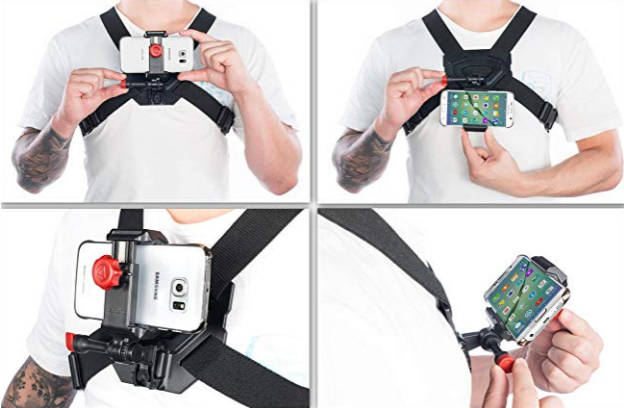
This will serve as the basic model of our wearable mount. The main problem we anticipate from this mount is rotation about the central mounting point. Ideally there should be two solid pieces upon which the mics are mounted, with straps connecting as well. This will consist of:
- Two rigid mount holders (metal, laser-cut acrylic, or similar)
- Webbing
- Buckles/straps
I also wrote code to generate the HINT test recordings. However, this is not completely practical to use yet, because there is not an interface for quickly switching between various SNRs – this is needed because the HINT is an adaptive test, switching SNR levels based on the subject’s success rates.
Goals for next week
- Build mount for microphones to attach to the purchased chest harness
- Create interface for running HINT given recordings
Kevin
Done this week
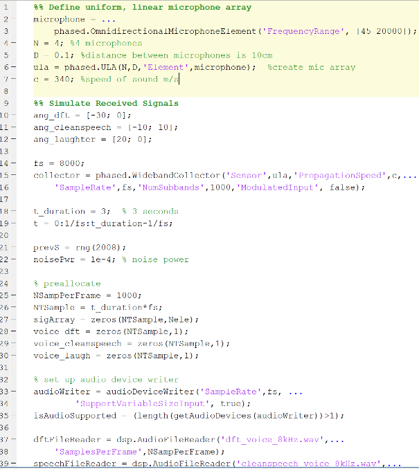
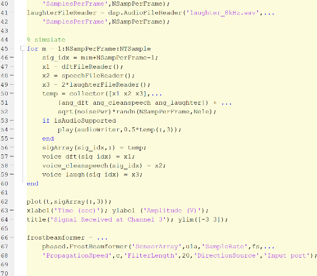
One of my goals for this week was to come up with a finalize an initial physical setup for the microphone array. I decided that for a linear array of n omnidirectional microphones with equal inter element spacing, the distance between each microphone element should be d=c/(2*f0)where c is the speed of sound and f0 is the midband frequency. Because the human voice frequency in telephony ranges from approximately 300 Hz to 3400 Hz, I chose 1800 Hz to be the midband frequency. As a result, the distance between each microphone was chosen to be 9.5cm apart. This means with a 4 microphone setup, we would require an array of 38 cm in length.
Additionally, regarding how each microphone input would be processed, the delay Tn between the desired signal arriving at the nth microphone and the signal arriving at the first microphone (at the origin of the coordinate system) is Tn =(n-1)*d*sin(ø)/c where d=9.5 cm and c is the speed of sound (343 m/s).
For signal processing, I have an initial MATLAB program which implements Frost Beamforming to try on our microphone setup. I have not done extensive testing yet on the adaptive beamforming code. This following week will be spent testing and modifying the beamforming code with (hopefully) real microphone input signals.
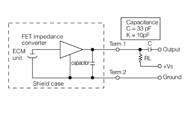
On the hardware side of things, I have worked in lab with Sean to create a temporary microphone setup for testing using microphones that were available from the past. The microphones we used for now are PM: WM-55D103. The specific circuit we made for each condenser microphone is shown in the figure below for testing.
Goals for next week
- Start building a setup rig with the harness that Bobbie purchased to create wearable microphone array
- Test adaptive beamforming algorithm on ideal generated signals
- Possibly move to real-input signals
Sean
Done this Week
This week, we put together a circuit for the microphones Professor Sullivan gave us and successfully got an analog signal read on the Teensy board. I just used simple analog read functions from the Arduino library to read sound levels. I also starting writing code using the PDM library to process the input from our surface-mount microphones
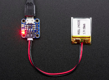
We decided to go forward with a rechargeable battery pack for external power, pictured below. In order to prevent damaging the board from supplying USB power and external power, I cut the trace between the two pads, to isolate the voltages. I will also cut the power line of the USB cord, just in case the trace isn’t completely cut.
I found tutorials for outputting high speed clocks from the Teensy, and will talk to Professor Sullivan more about these methods.
Goals for Next Week
- Read digital signal on board
- Decide on mic driver clock method based on usability, jitter, and accuracy