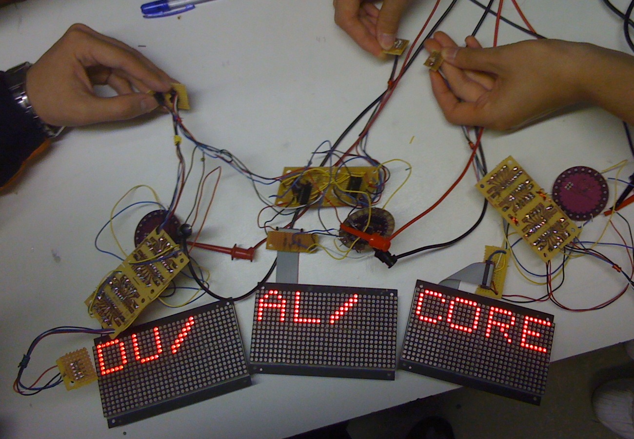
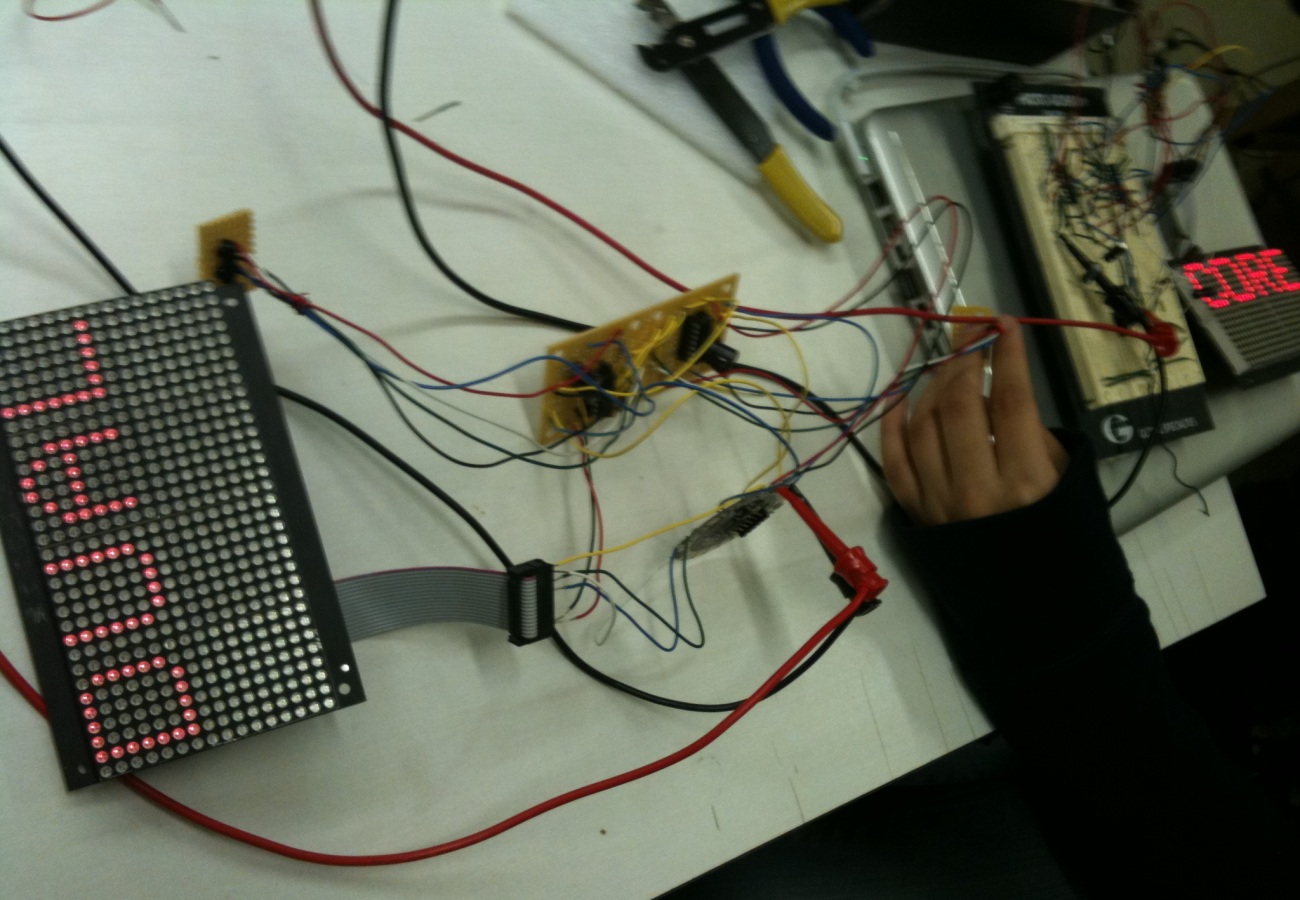
Light up the LED board.
This is the first digit displayed on our LED board after successfully setting up the conncection between lily pad and LED board.
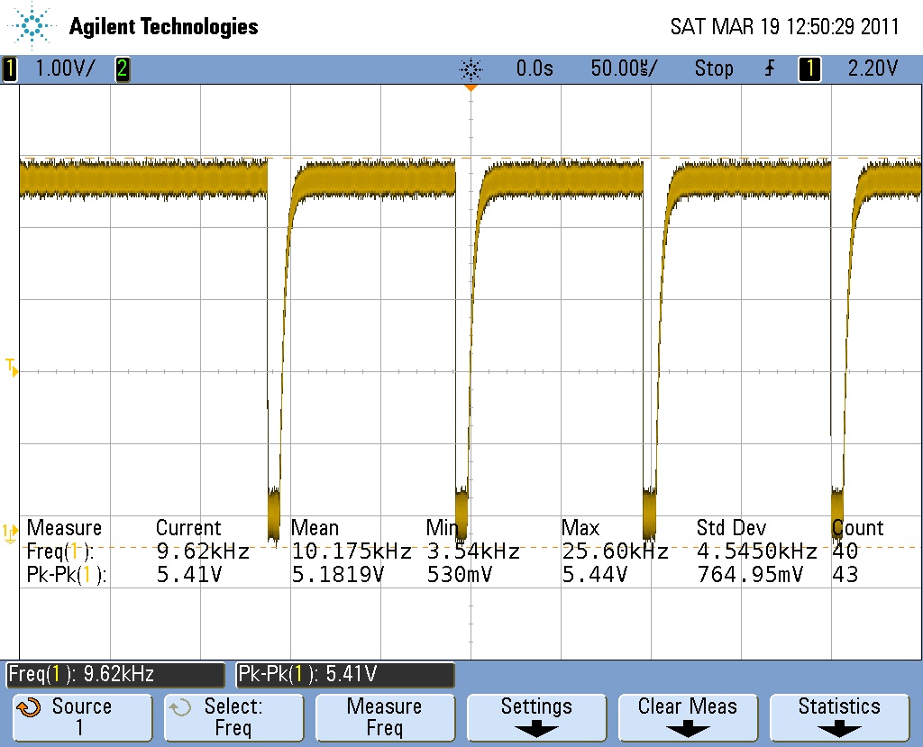
Debug the Irda signal transmission.
This is the oscillioscope screenshoot of RXIR with the other not sending signal.
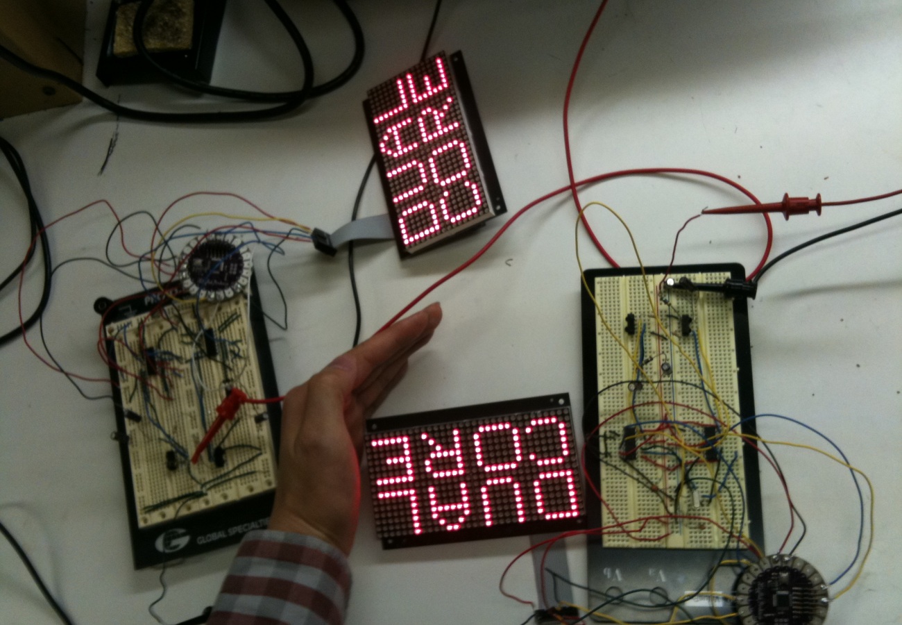
It's Working!
After some excessive testing, our system is now working in a basic model. If set up two boards and preload a 8 char long string to the buffer: "DUAL CORE". As you can see, according to the board position, the string is split into two even parts. The left board shows "DUAL", while the right board shows "CORE".
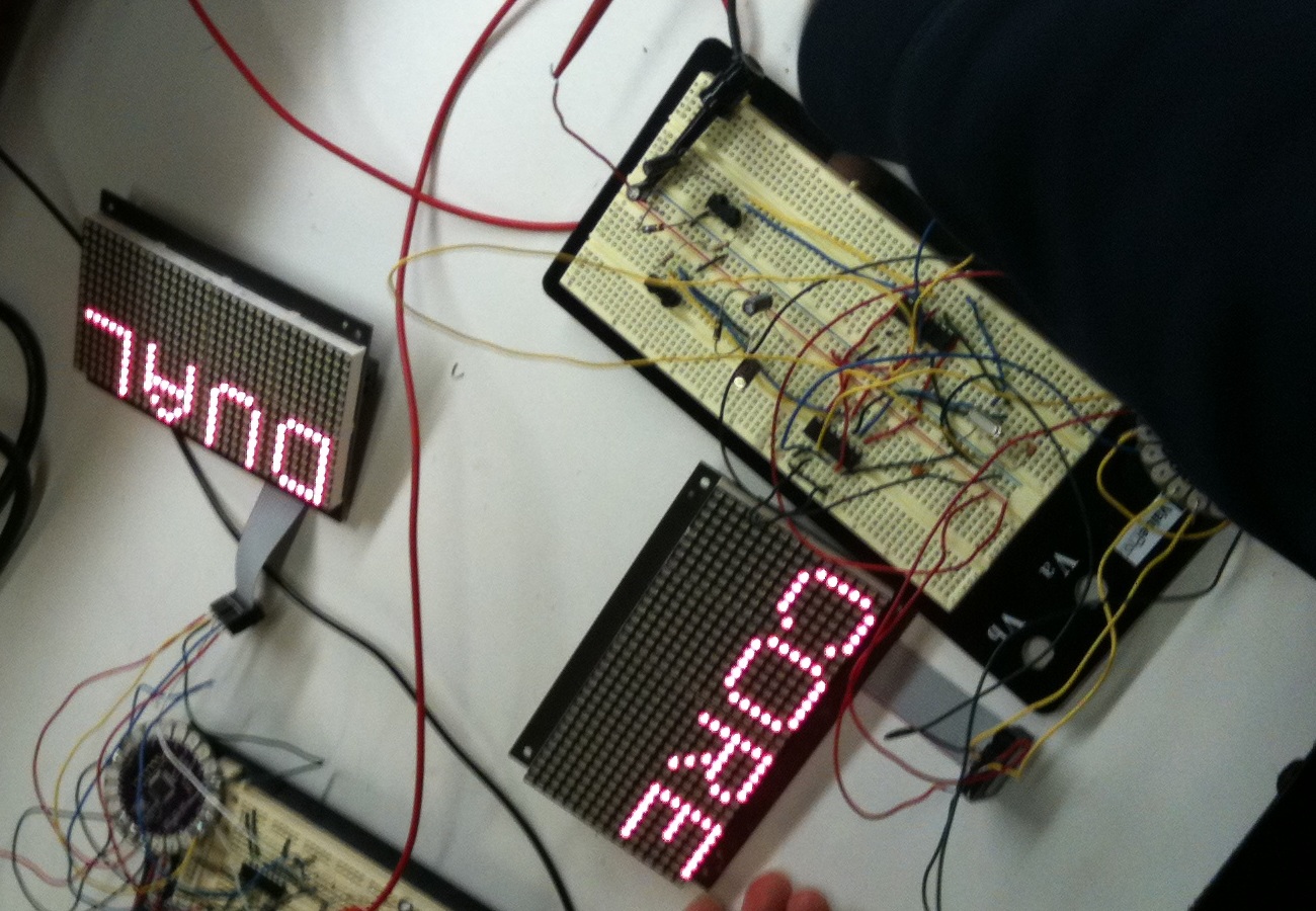
How About Blocking the Signal?
Now we manually board the infrared ray by using human body. While the signal is blocked, the boards no longer receive position report from the other boards and consider itself the only board existing. So it will print the whole message: "DUAL CORE".
Move onto the PCB.
While using the protoboard, our system is extremely unstable (You won't believe the arduino get stuck every 20 seconds...). So the team decided to move all the devices on to the PCB and solder them up.
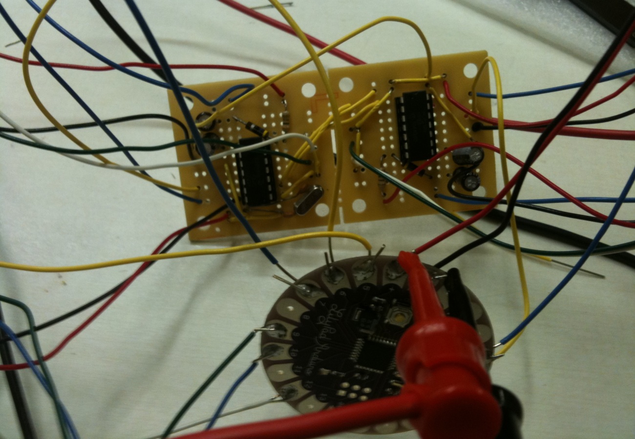
PCB design.
This is the diagram of our PCB design. We set up all the connections here.
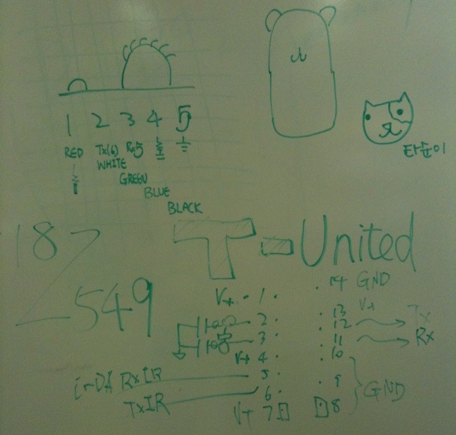
Here Comes the Stable Version!
Now everything is wired up. We again test the system and now it works for more than two minutes without breaking down. With the compact design, we can further attach the system onto a cap.
In Shape.
This is a brief view of how our system will look like. With two IRDAs on the side, the cap will be able to determine the position, and then display the corresponding part of the message. This is our No.1 model and a few more will soon follow!
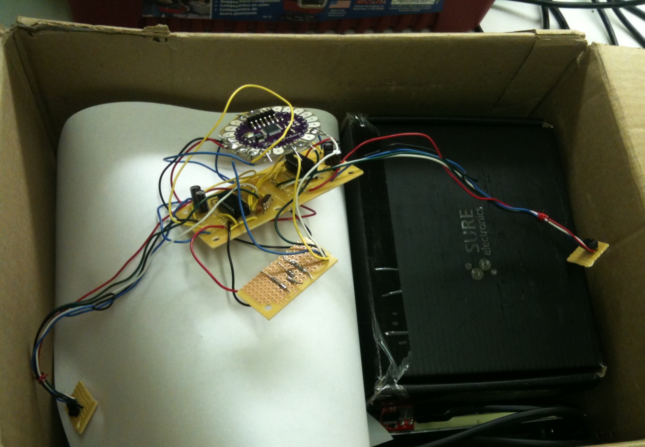
Welcome model No.3.
We have now finished all the soldering, and our system of three caps can now recognize each other and display correct message according to position.
