Shravya’s Status Report for 10/05/2024

This week

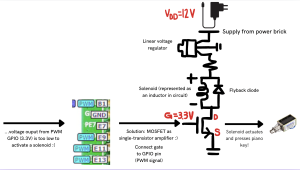
As a recap of what I touched on last week already: An STM32’s GPIO pins have a 3.3V output, but a push-pull solenoid may need 12V. Therefore, we will need to have the STM32’s GPIO pin output of 3.3V function as an enable line to control whether a solenoid is on/off, rather than serve the purpose of a supply voltage. We can feed the 3.3V into the gate of a MOSFET to do this.

We had always agreed on the circuit diagram. However, Peter assumed we would use a PMOS, and I assumed we would use an NMOS. An update from this week is that we resolved this confusion. In our circuit diagrams we had placed the MOSFET between the solenoid and ground. In this case, it is correct to use an NMOS as an NMOS gate-source voltage being higher than the threshold voltage enables the device, and the NMOS acts as a low-side switch since it completes the rest of the circuit’s connection to ground. A PMOS would work in a similar way as a high-side switch if it was placed immediately below the power supply, because a PMOS turns on when the gate-source voltage is more negative than the threshold voltage (Vth). It was easier to keep the circuit diagram drawing we already did (with the MOSFET connecting the solenoid to ground) as is, and we simply made sure the MOSFET icon was an NMOS not a PMOS.

According to the schedule, this week I was supposed to run Cadence simulations regarding the circuit, and so I did.

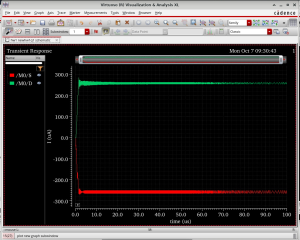
I had to conduct (refer to plots):

  1. Transient Analysis/time-domain simulation:
  • Verify the voltage across the solenoid is 12V when the NMOS is fully on.
  • When the NMOS turns off, ensure the flyback diode handles the transient current spike from the solenoid without issues.

2. DC operating point analysis:

  • Apply a 3.3V GPIO signal to the NMOS gate, verify it turns on and off correctly. Measure the current through the solenoid (it should reach 250mA).
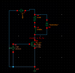
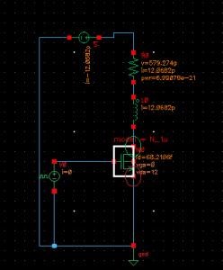
This was the intended circuit. However, ADEL cannot generate any netlists/run any simulations as there is no built-in model card for diodes. When I tried to add in some model cards I downloaded online, I got errors + troubleshooted, but ultimately had to take out the diode.


The transient analysis shows that, as expected, 250 mA of current pass through solenoid and that the switching behaviour is quite instantaneous.
Annoted with DC operating points

On an aside, I am curious to understand why, fundamentally, there is a transient current spike when solenoids turn off. Not that this is too important for the project, but I want to know more for my own general ECE knowledge.


Next week

I will start familiarising myself with Python’s MIDO library to parse + convert MIDI file data into a bit-packet format that is suitable to feed into the STM32 for solenoid actuation.

Peter’s Status Report for 9/28/2024

This Week

The majority of this week was spent researching solenoids and finding an affordable solenoid to fit our design requirements. I determined that we needed a push solenoid with a stroke length over 4mm (the travel depth of a membrane keyboard’s keys), to ensure notes can be fully depressed on a keyboard, and a duty cycle close to 100%, without being too expensive (preferably under $15), since we would need 13 solenoids for the final product. The solenoid with part number 412 from Adafruit Industries is documented to fulfill all of these requirements, with a 100% duty cycle and cost $7.50 each (without factoring in tax or shipping). A purchase order for 2 Adafruit 412 solenoids was placed on Wednesday so that we may test the solenoids to ensure they meet our requirements.

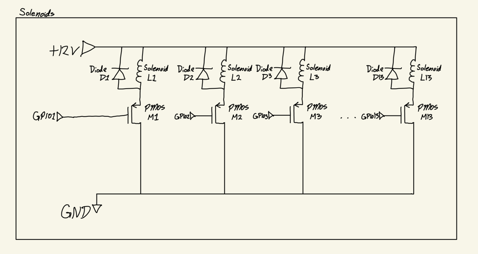
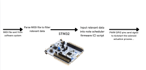
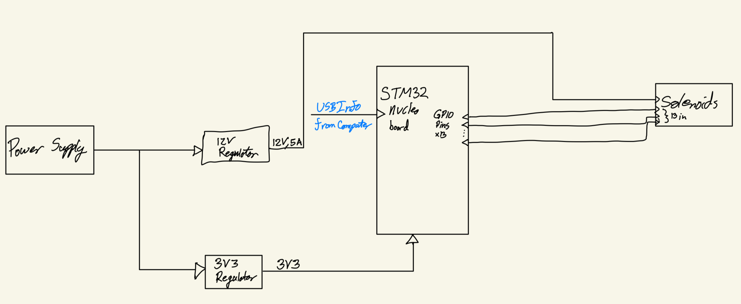
Additionally, I created a more detailed block diagram for the hardware aspects of the product, see Figure 1, and created a schematic to implement the 13 solenoids based on the Adafruit 412 documentation [1], and my report from last week where it was discussed that a PMOS’s gate may be used as an enable line, see Figure 2.


Figure 1: Hardware Block Diagram

Figure 2: Solenoids Schematic

While I am on track currently, the delivery date of the solenoids may cause some delay in the testing and further development of our design. If this occurs, I can begin work on the 3D model for the solenoid’s case early. Additionally, Shravya and I could go over our designs together and model how they may interact to be better prepared for when the solenoids arrive.


Next Week

In the coming week, I plan to test the solenoids with Shravya, and test our circuit designs. Additionally, I want to spend more time looking over Shravya’s solenoid circuit design that uses an NMOS for a common source amplifier and compare it to the PMOS design in Figure 2.


[1] “412_Web.” Adafruit Industries, 12 Oct. 2018. https://mm.digikey.com/Volume0/opasdata/d220001/medias/docus/21/412_Web.pdf

Team Status Report for 09/28/2024

As a group, we spent a lot of time this week on our design review presentation. We have also made some progress on the project itself: Fiona has been getting familiarized with an OpenCV eye tracking program, Shravya has come up with a preliminary design of the solenoid control circuit, and Peter has been researching components to order. Each of our personal reports will delve into more detail on those fronts. 

This week we ordered two push-pull solenoids (Adafruit 412) that we had shortlisted (one for testing and one as a back-up). We plan to figure out how to program them and verify that their properties (e.g., sizing, depth of press, latency and power consumption) are suitable for our use case and design requirements. If so, we will order more.

Risks

We are concerned that when users unintentionally move their heads, despite continuing to look in the same area, the system may register it as a change in eye movement and record a wrong command. Even with that risk mitigated by the wait time to confirm a command, this may make the user experience tedious, so we plan to have slack time after integrating each part of the system together to deal with bugs like these that might come up. We are also hoping to do some preliminary testing with the eye-tracker with just squares on a screen (rather than our unique UI commands) to identify any problem such as these as early as possible.

Changes to Design

We were originally thinking of using a custom PCB to keep our circuit components neatly organized, but we want to pivot to using a solderable breadboard as it is easier (i.e., no need for PCB layout) and allows for more iterations.

Schedule Updates

Fiona redesigned and reordered most of her application tasks for the coming weeks.


Part A: Public Health, Safety, and Welfare, Written By Fiona

Music can be extremely beneficial to mental health; it can be used in therapy and is also a very common hobby. For many, music is a tool to better their mental health, like sports, reading, or other types of art. It is an important part of life for many people, not just professional musicians, and our project is intended to make the enjoyment of music more accessible, so we believe that it has the potential to better the mental health of a broader range of people.

Part B: Consideration of Social Factors, Written By Shravya

Our project provides a more inclusive way to engage with musical instruments like the piano, giving users with impaired hand/arm mobility an opportunity to express themselves and participate in an art form that might otherwise be inaccessible to them.

Beyond being a personal creative outlet, this project reflects broader trends of inclusivity and accessibility in design. The music industry, like many others, can sometimes marginalize those with physical limitations, and this product aims to reduce those barriers and expand participation. In human history, music has always been an avenue for fostering social connections, transcending language + cultural barriers, and is an integral part of many social gatherings. Individuals who were previously excluded from music activities will now be able to engage, contribute, and form connections within musical communities. 

Part C: Consideration of Economic Factors, Written By Peter

We aim to reduce the price of our product without sacrificing functionality. For the housing of the electrical components that go over the piano keys, we are doing this by 3D printing the body. This in-house manufacturing method cuts the costs of paying a manufacturer, and keeps the weight of the unit down. Additionally, once testing with breadboards is completed, PCBs, of an identical design, could be ordered in bulk with pre-placed parts that can be done cheaply overseas. Additionally, the UI utilizes a computer, which most people already own, further reducing the price to utilize our product.

Shravya’s Status Report for 09/28/24

This week, my primary focus was on preparing for the design review presentation. As part of this effort, I created the hardware system block diagram, which outlines how the different components of our project will interact with one another- find attached below. Additionally, I worked on designing the electrical circuit (visible in the second image) for the solenoid control system. This design includes obvious components, but I’ve realized that integrating MOSFET amplifiers is critical to making the circuit function properly. This is because the signal output by the GPIO pin is 3.3V which is too low of a voltage to input into solenoids + activate them. Hence, a common source NMOS configuration can amplify.

Unfortunately, I fell slightly behind schedule this week due to two midterms and the preparation required for the design presentation. I wasn’t able to begin running the Cadence simulations, as planned, but I will prioritize this first thing next week. To catch up, I’ve already blocked out additional time to focus on running these simulations and ensure the electrical circuit I designed operates as expected.

Next week, I plan to finalize and run the simulations in Cadence, ensuring the circuit is functioning as intended. Additionally, I will focus on learning more about how Pulse Width Modulation (PWM) works and how it can be integrated into our system to improve power efficiency. I’ll be working with Peter to begin testing how one solenoid works.

Fiona’s Status Report for 09/28/2024

This Week

Eye Tracking [1][2]

I was able to set up live-video eye tracking locally on my computer with the help of the research I did last week [1]. I did so by copying over the code [2] and ensuring each step worked with my personal computer/set-up.

I extended some extra time to this process to make sure I understood what the code was doing, because we expect to have to modify some of it to integrate it with our user interface. Also, there was some debugging necessary to get the program to perform as expected, and I needed to modify the code in some places for testing.

I did run into some trouble setting up the threshold (a value to manage differences in lighting) “track bar” that was in the original project, maybe due to the fact that the cv2 library could have changed this functionality since the article and code were published in 2019. During testing, I changed the threshold value manually in the code, but I believe that I should be able to set up a track bar (or some other type of user input) while implementing the user interface.

There were a few differences I noticed while setting up the code. For example, the author of the article suggested that we cut eyebrows out from the eye block detected by the computer, but when I was testing with my face, the eye-detector did not include my eyebrows in the detection area. I wonder if different face structures produce different results in this area, so I would like to test the design on more people in the coming weeks.

Design Review

In preparation for the design review, I made a block diagram for the software side of the project, because I wanted to make sure that there weren’t any facets that were missed in our planning that we would later need to implement in a rush because we forgot. There are a lot of moving parts in the software side of the system.

After making this diagram, I realized I needed to reorder and redesign my tasks in the Gantt chart and to better fit the dependencies and difficulty of each task. Here are my new tasks for the next five weeks:

I was fairly busy this week, so I didn’t get as much coding done as I wanted to. However, I think that refining the software layout was a helpful first step towards the coding process.

Next Week

Based on my new schedule, I want to start working on the frontend next week. I have already done some preliminary research on GUIs in Python this week, but haven’t decided which library (of the many available) will best fit our needs, so that will be part of the process.

One of the most important parts of this step is to identify the coordinate ranges for each command to set myself up for success in the week afterwards, where I want to make the code convert coordinates to commands.

Another thing happening next week is the design presentations. After we get our feedback, we will review it and determine what changes we want to make while writing the Design Report, which is due at the end of Week 7.

[1] Filonov, S. (2019, Mar 22). Tracking your eyes with Python. Medium. https://medium.com/@stepanfilonov/tracking-your-eyes-with-python-3952e66194a6

[2]  Filonov, S. (2019, Mar 22). Eye-Tracker. GitHub. https://github.com/stepacool/Eye-Tracker/blob/No_GUI/track.py

Fiona’s Status Report for 09/21/2024

This Week

Most of my time this week was spent on the proposal presentation slides and preparing to present them to the class. 

In preparation, I conversed with my group members to ensure that I was able to fully represent our project to the class, and make sure we were on the same page for every section of the proposal. Primarily, I wanted to make sure that we had a full plan for carrying out testing on the system because I wanted to be able to explain it well to the class and we hadn’t explored that area as much in our previous discussions. 

I also helped refine the script we started working on last week to ensure it contained all the information we wanted and memorized it. I practiced the full script several times, first with Shravya and Peter, and then with my roommate, as well as multiple times on my own. 

After presenting, I was able to allot some time to researching eye-tracking with OpenCV. I went back to a resource [1] we identified while preparing our abstract, and summarized it down into actionable steps for us to pursue while implementing eye-tracking. According to the resource, we should cut the process into discrete steps: first identifying faces, then eyes, and then pupils, and also implementing the identification on still images before video [1]. I think this is a promising software we should start testing with immediately.

I am behind the schedule we set in the proposal, because I was not able to find the time to work on the UI backend this week. 

Next Week

Next week, our group will be working on the design presentation; we will expand on our proposal with the research we’ve completed and incorporate the feedback we received on the proposal, as we see necessary. I will assist my group members in this.

Since I have fallen behind, I will start working on the UI backend next week, along with the code to convert eye-commands to MIDI file format. After I start working on this software, I believe I will have a better idea of whether I need to re-evaluate my tasks on the Gantt chart. If necessary, I will re-define my tasks for implementing the UI in the chart before we present the design review. 

References

[1] Filonov, S. (2019, Mar 22). Tracking your eyes with Python. Medium. https://medium.com/@stepanfilonov/tracking-your-eyes-with-python-3952e66194a6

Team Status Report for 09/21/2024

A significant risk we are taking on is the inclusion of eye-tracking in our product’s design. No one on the team has background experience using or creating eye-tracking software, but we believe there will be ample time to learn since we are starting early. Additionally, we expect to be able to find open-source resources to customize for our system.

Figure 1: Block Diagram

In preparation for our proposal presentation, we finalized our use case requirements, block diagram design (Fig 1), and testing plans.

One question we received from professors/TAs after our presentation was whether we plan to implement varying pressures on solenoid presses. We will keep this suggestion in mind, and may consider it for future implementation after ensuring all other features are fully operational. It could help the piano output sound more realistic and humanized. 

We made a minor edit to the schedule: Peter took over the task “Research solenoid and solenoid control” because he is doing the schematic and layout for solenoid control. 

Figure 2: Gantt Chart

Shravya’s Status Report for 9/21

At the beginning of this week, I helped polish the Proposal Presentation slides. Specifically, I worked on defining the technical challenges (both hardware and software), specifying testing methodology + performance metrics for different parameters (accuracy, eye-tracking detection latency, solenoid latency, and power consumption) and contributed to shaping the overall structure of the Gantt chart. I also participated in preparing Fiona for the oral presentation; Peter and I spent about 2 hours to help her practice her public speaking skills as well as refine her script after seeing the first round of presentations on Monday.

I began research on the power management system for the solenoids, which is critical for ensuring stable and efficient operation. Since solenoids require precise voltage and current control, I’ve been exploring different power management circuits and components.

In order to integrate Low Dropout Regulators (LDOs) -a type of linear voltage regulator- into our solenoid power management system, I have been studying the LM7805 in particular. Our case is such that the input voltage is only marginally higher than the intended output voltage, which is a perfect fit for LDOs. This is essential to guarantee that the solenoids receive a steady, uniform voltage; variations may cause irregular key presses or deterioration of the solenoids over time.

I’ve also decided that it would be beneficial to include decoupling capacitors in our custom PCB to stabilize the voltage supply and prevent noise that could affect solenoid performance. This is a very standard practice for PCB design.

Moving forward, I need to narrow down the specific components for the solenoid control circuit and run initial simulations to ensure everything will function as expected. These simulations can be done in Cadence Virtuoso ADE. I can start by running transient analysis to simulate how the voltage and current evolve over time, especially as the solenoid is actuated. It’s important I simulate a single solenoid actively pressing as well MULTIPLE solenoids simultaneously pressing, as we are going to be implementing chord functionality (up to three simultaneous notes).

The waveform viewer will also be useful to check for any instability (e.g., fluctuating voltage or high power dissipation). For my simulation data to be useful, I need to first know which particular solenoid components we plan to order (I need to make sure the current and output voltage from regulator don’t exceed solenoid’s maximum ratings). Thus, I suppose one dependency I have here is for Peter to finalise some preliminary component selections as he is the one in charge of selecting which solenoids we will use.

We will also be working on the design review presentation this upcoming week.

I am on schedule at the moment, but I’m aware that this is the point in the semester that the project starts to get busy as we are going to begin with the true, hands-on engineering.

Peter’s Status Report for 09/21/2024

This Week

The first half of this week was spent preparing for the proposal presentation and working together as a team to ensure we knew our product well going into the presentation. Post-presentation, we altered our Gantt chart to put me in charge of researching solenoids and solenoid control. What I have learned is that there are some solenoids that pull and some solenoids that push and pull, aptly referred to as push-pull solenoids. Push-pull solenoids are the type of solenoid we will be using for our project, as we require solenoids that can push the piano keys down when powered. 

GPIO pins of an STM32 can output 3.3V, but a push-pull solenoid can require 12V. So, in order to control a solenoid with GPIO pins from an STM32 chip, as we plan to do, we will need to have the STM32’s GPIO pin output of 3.3V act as an enable line. One way to do this may be through using a PMOS’s gate as an enable line.


Next Week

Schematics will be made for the solenoid system of solenoid control, along with calculations to justify the design. These should be completed by the end of this upcoming week (week of 09/22/2024). I will also speak with Shravya about her plans for power management to ensure that our designs will work well together.

As a team, we will be working together on the design presentations.

I am on schedule currently and am prepared to allot more time in the coming week towards designing the solenoids control system.