Fiona’s Status Report for 10/05/2024

This Week

Design Presentation

This week, I helped my group members with our presentation slides and script for the design review. I also helped Peter prepare to present our design review to the class.

User Interface [1][2]

I also started working on programming our user interface in Python. To do so, I had to do some research on Python’s built-in GUI library, Tkinter, which I hadn’t used before. Fortunately, I was able to find two very helpful resources/documentation that really helped familiarize me with the way the library works [1][2].

I was able to create a preliminary UI, however, I had some trouble figuring out how to adjust the physical sizes of facets of the UI, which is important to our design, given that the buttons cannot be so small the eye-tracking software cannot determine when a user is looking at them.

I decided to put that issue on the back burner for the time being, and programmed each of the eye-commands to be buttons, which can take a function input in Tkinter. This will make it easier to write and test the command response backend code in the future, without having the full eye-tracking program written. What I mean by that is, with the button functionality, we will be able to test that the program is writing to the MIDI file and performing other commands by clicking on the screen, rather than first needing to integrate with the eye-tracking software.

Next Week

I am behind where I wanted to be at the end of this week, because of the trouble I had with the UI, but I hope to get caught up on that work next week.

I expect that most of my time next week will be spent on the design report. Specifically, I plan to do more research on what academics have experimented with for eye-tracking programs and hopefully use those to make informed decisions on how to write our software, all of which I will document in the design report.

Also I would like to complete my Gantt chart task for next week, which is to map coordinates to commands in the code.

[1] Shipman, J.W. (2013, Dec 31). Tkinter 8.5 reference: a GUI for Python. tkdocs. https://tkdocs.com/shipman/tkinter.pdf

[2] Graphical User Interfaces with Tk. python. https://docs.python.org/3.9/library/tk.html

Shravya’s Status Report for 10/05/2024

This week

As a recap of what I touched on last week already: An STM32’s GPIO pins have a 3.3V output, but a push-pull solenoid may need 12V. Therefore, we will need to have the STM32’s GPIO pin output of 3.3V function as an enable line to control whether a solenoid is on/off, rather than serve the purpose of a supply voltage. We can feed the 3.3V into the gate of a MOSFET to do this.

We had always agreed on the circuit diagram. However, Peter assumed we would use a PMOS, and I assumed we would use an NMOS. An update from this week is that we resolved this confusion. In our circuit diagrams we had placed the MOSFET between the solenoid and ground. In this case, it is correct to use an NMOS as an NMOS gate-source voltage being higher than the threshold voltage enables the device, and the NMOS acts as a low-side switch since it completes the rest of the circuit’s connection to ground. A PMOS would work in a similar way as a high-side switch if it was placed immediately below the power supply, because a PMOS turns on when the gate-source voltage is more negative than the threshold voltage (Vth). It was easier to keep the circuit diagram drawing we already did (with the MOSFET connecting the solenoid to ground) as is, and we simply made sure the MOSFET icon was an NMOS not a PMOS.

According to the schedule, this week I was supposed to run Cadence simulations regarding the circuit, and so I did.

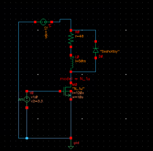
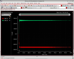
I had to conduct (refer to plots):

  1. Transient Analysis/time-domain simulation:
  • Verify the voltage across the solenoid is 12V when the NMOS is fully on.
  • When the NMOS turns off, ensure the flyback diode handles the transient current spike from the solenoid without issues.

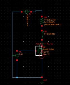
2. DC operating point analysis:

  • Apply a 3.3V GPIO signal to the NMOS gate, verify it turns on and off correctly. Measure the current through the solenoid (it should reach 250mA).
This was the intended circuit. However, ADEL cannot generate any netlists/run any simulations as there is no built-in model card for diodes. When I tried to add in some model cards I downloaded online, I got errors + troubleshooted, but ultimately had to take out the diode.


The transient analysis shows that, as expected, 250 mA of current pass through solenoid and that the switching behaviour is quite instantaneous.
Annoted with DC operating points

On an aside, I am curious to understand why, fundamentally, there is a transient current spike when solenoids turn off. Not that this is too important for the project, but I want to know more for my own general ECE knowledge.


Next week

I will start familiarising myself with Python’s MIDO library to parse + convert MIDI file data into a bit-packet format that is suitable to feed into the STM32 for solenoid actuation.