Jack’s Status Report 12/7

I was pretty busy due to finals and other projects. However, I still got most of the items on the Gantt chart done. The main issue we encountered was a lost part.

This week, I printed out the parts for the Z-axis assembly and got some assembly done. However, We are not able to find the lead screw that we stored in HH 1307 to continue. I am planning on using a lead screw mechanism I had from a previous project to fill in the gap.

I also helped the team reconfigure the camera to get lower latency. While we are still not able to hit 100ms latency, we lowered it from above 300ms to just below 200ms. This is all achieved by switching the codec to compress frames individually, so that the camera does not have to wait for multiple frames to be buffered before streaming the video. This required quite a lot of research to find the best streaming codec for latency. We ended up deciding on trying to switch the camera to MJPEG, a format commonly supported by webcams. We were also not sure how to change the streaming codec of the camera. The documentations on this topic from the vendor were very sparse. The pdf version of the document did not match the output we were seeing from the debug messages. Finally, we were able to find out how to do this by consulting a SQL database embedded in the vendor SDK.

Jack’s Status Report 11/30

  • Testing & Validation
    • In order to test the gripper force output against the design requirement of 6N, I borrowed a spring scale and grabbed the scale with the gripper. The gripper is able to output 8.5N, exceeding the design requirement.
    • In order to investigate the latency of the system, I came up with the idea to record the camera output along with the user moving their hand. From this, we were able to determine that most of the latency came from the depth camera. This led to us deciding to switch to a regular webcam, which does not need to process the frames to get depth, reducing latency. Depth can instead be obtained from the ARUCO tag detection algorithm.
    • I worked with the team to also test quantiative metrics including precision, payload and speed.
      • For precision, we fixed a pen to the robot and drew lines on a piece of paper. The dimension of the lines were compared against commanded movements. We were able to reach +-1mm precision, exceeding our original requirement of 2mm.
      • For speed, we commanded a fixed distance and recoreded the robot’s moves with a stopwatch in the frame. Speed could then be found from dividing the distance travelled with the time taken. While we were able to reach the design requirement of 100mm/s by tuning the software parameters, we found this speed to be too fast for the use case: jittery inputs are amplified due to the high speed.
    • Some pictures from testing:
  • I designed the new Z-axis mechanism, and printed the parts for them. I plan on adding these parts and finishing up the Z-axis mechanism next week.
  • I also came up with a new way to control the force output of the gripper beyond binary open/close. This involves adding a foam pad to the grippers and measuring the relationship between compression of the foam and the force at the gripper. This relationship is most likely a linear function, if we model foam as an ideal spring. A limit switch will be used to detect an object making contact with the gripper. This way, when contact is made initially, the postion of the gripper is recorded. Force can then be controlled by advancing the gripper position past the initial contact point. How much to advance the gripper position is known from the force-position relationship measured.

Jack’s status report 11/16

  • Progress This Week:
    • Completed software integration for the gantry system. I spent a lot of time on this task due to an unforseen latency issue.
      • When a movement command is sent to the driver, there is no way to interrupt it.
      • As a result, if the user moves their hand quickly in one direction and moves their hand back, the robot will finish the first command and move all the way to one end of the axis before moving back.
      • This results in a lot of latency. Furthermore, when the user moves faster than the robot can keep up, the robot “remembers” the moves and executes each of them instead of going to where the user’s hand is currently located
      • I looked into ways to interrupt a command in progress. However, this was simply not supported by our driver board.
      • I devised a solution to break down a movement command into many tiny movements instead of one command to move a long distance.
      • The PC will only send a command when the previous one finishes.
      •  When the user moves their hand, the movement is decomposed into many small steps and queued.
      • A separated thread executes queued commands
      • When the user moves their hand again and the position updates, the queue is cleared.
      • This approach works. Currently, the latency is still noticeable but is much better.
    • We reassigned integration of the gripper to Leland
    • I built a new controller housing to accomodate the esp32 and the ARUCO tag.
    • Leland’s camera stand has not arrived so I built one from scratch.
    • during integration test, we found that the gripper could grip a 500g water bottle by the cap reliably.
    • Gantry movement was reasonably smooth. The speed is a bit slower than I expected so I designed a different pulley. It will be added after MVP demo.
  • Goal next week:
    • optimize gantry software to reduce latency
    • add force sensing resistors to the gripper to do force-sensitive control
    • assemble z-axis mechanism
  • Verification plan for gripper system:
    • use case requirement: be able to move 300g payload
      • This will be tested using a water bottle whose shape roughly matches a typical beaker. Performance of a gripper can vary a lot based on where the gripper makes contact. For the payload requirement, I think I will specify that the gripper engages with the middle of the bottle, as opposed to grabbing it by the lid.
    • design requirement: be able to output 6N force at the gripper
      • This will be verified using a kitchen scale. The gripper will grab a kitchen scale at full force.
  • Verification plan for gantry system:
    • design requirement: position repeatability of 2mm:
      • This will be tested using a testing script that commands a fixed set of movements on the gantry. At fixed intervals, the testing script will stop the gantry briefly to allow us to use a pen to mark its position on a piece of paper.
        • The dots on the paper will be measured against the commanded movements
    • design requirement: speed
      • speed requirements will be verified using a video recording. A testing script will command a movement along each axis for a fixed distance. Time to execute the movements will be used to calculate the average speed.

Jack’s Status Report 11/9

  • Progress This Week:
    • Designed wrist coupler to connect wrist motor to gripper
      • currently 3D printing
    • Assembled exisiting parts. Ran into some issues so I spent significant effort on iterating the hardware.
      • The new linear slides I ordered arrived!
      • Assembled XY mechanism. However, some parts did not fit properly. Nonetheless, we were able to confirm that the gantry was smooth and had no perceptible sag or slack.
      • I used some hacks such as using fewer bolts than the designed number to make everything fit. However, I decided to redesign them so that they work properly.
        • Redesigned hardware are printing overnight.
      • The gantry+gripper hardware should be ready by Monday.
    • Force control on gripper
      • For the MVP, we decided to not incoporate it because binary open/close modes should suffice for rigid objects. However, we still want to pursue force control for the final product.
      • Researched using Dynamixel smart servos to achieve torque control for the gripper. Sifted through documentation on all the models and reallized the cheapest model that offered torque control was $300.
      • Pivot towards homebrew mechanisms
        • Idea 1: same as originally proposed. Use torsion springs to act as a compliant mechanism
        • Idea 2: modify gripper mechanism to incoportate springs into the gripper.
        • Idea 3: use FOC (Field Oriented Control), an algorithm that achieves torque control in steppers by modeling the electromechanical fields inside the motor and energizing the windings to control the torque output.
    • Goal next week:
      • complete software integration for the gantry/gripper. Currently, I have software that can control the gantry. However, I expect to put  a significant amount into integration. Now that Leland is able to get XY coordinates from the CV stack, and Zhenghao has solved the FSR reading problem, all indiviudal software subsystems are in place.
      • Design and build new handheld controller housing.
        • We decided to pivot away from the PVC pipe chassis, as the electronics are occupying more room than we originally expected.
        • This is not crucial to the MVP, but we would like the MVP to look as mature as possible.
    • Gantry assembly so far (x-axis belt not added due because I had to reprint a part in the x-axis mechanism)

Jack’s Status Update 11/2/2024

  • Work this week:
    • rethinked the approach for the gripper. Originally, I was going for a spring mechanism: the motor winds up the spring after making contact with the object, and force is controled by how much the spring is wound. The issue is that it is mechanically complex. I was not able to come up with a good implementation of this concept.
    • If I can control the amount of torque at the motor directly, I don’t need a spring mechanism.
    • Currently, I am looking into smart servos that can do force control, such as the Dynamixel series: https://www.robotis.us/dynamixel/?srsltid=AfmBOoqgSxak-qbqm3m2aevmbsqF1EVobBmwjjBQxEVpmByu927cBMaB
    • I am also looking into using stepper motors and BLDC motors: https://docs.simplefoc.com/torque_control
    • I also added a design requirement for gripper force:
      • 300g payload * 10m/s^2 = 3N gravity force. Typical static friction coefficient value for glass on metal contact is 0.5. We will have a higher coefficient of friction because we plan on using rubber for the gripper. However, I will use 0.5 to be safe. This means we need 3N/.5 = 6N normal force at the gripper.
      • The gripper design we chose (https://www.thingiverse.com/thing:2661755) uses a rack-and-pinion setup. The pitch diameter is approximately 1.2cm. This means the torque required at the motor will be 6N * (1.2cm/2) = 3.6 Ncm
      • for example, typical servo motors such as https://tinyurl.com/yc4nuvbe has 12kgcm of torque, or about 120Ncm. Therefore, there will be more than enough torque.
    • Conclusion: I can use a regular servo motor, or a DC motor. Originally I thought torque requirements meant I could only use a DC motor.
    • designed and printed motor brackets for the gantry: 
    • Modified an existing design for the gripper, built and assembled. This gripper only supports position control, not forrce control. For the MVP this might be sufficient. I tested this on some common household objects and even without a rubber sleeve, the gripper will be able to hold on to most objects with a flat side. (round objects are more difficult, but adding a rubber sleeve should alleviate that)
    • Finished design of X and Y axis 3D print parts. I have attached a particular difficult part, as well as the overall assembly below. Pulleys and belts are not shown because I don’t know how to model belts in SolidWorks.
    • Currently, I am working on designing the wrist and Z-axis mechanism for the gantry.
    • My goal for the next week:
      • finish building the XY parts of the gantry and attaching the gripper to it.
      • design and print wrist roll joint mechanism.
      • write firmware to control gripper motor
      • have a working gantry system consisting of X, Y, wrist and an open/close gripper. This will be our MVP configuration. For the final product, I will need to add Z axis and force controllable grippers
      • the MVP gantry will be able to communicate to the central PC via serial. It will be able to execute move and grip commands.

Jack’s status report 10/26/24

This week, all the parts for the gantry, except the linear slides, arrived. I am still working on designing 3D-printed brackets for the gantry mechanism. However, I wired up the electronics and deployed my exisiting software work.

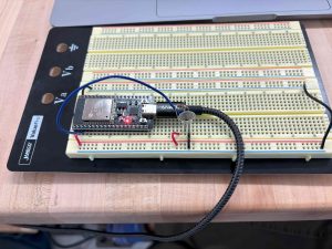
I was able to set up force-sensing resistors and read values from them on an ESP32.  Characterizing relationship between voltage and force might require some data collection, since the vendor documentation is somewhat lacking. This took longer than expected because of difficulties in finding the right toolchain for flashing my code to the ESP32. I ended up using Arduino IDE, but I would like to set up the ESP-IDF library and toolchain at some point.

I also completed the software for sending position commands to the stepper motors and wired up the stepper motors and demo these commands. The choice to use 3D printer driver boards really sped up the whole process compared to using individual motor drivers: all I needed to do was plug in the motors and send Gcode commands over serial .The power supply arrived, but the casing was damaged so I was not sure if it was safe to use since the casing is metal. However, I was able to overcome this by susbstituting the power supply module with a laptop charger.

My goal next week would be to finish building the XY axes of the gantry, including 3D printed parts. I am also aiming to build a prototype gripper mechanism.

See the stepper motor setup here:

https://drive.google.com/file/d/1oAM67E24leO2Pc1g6S6h67MTfPZt7vkb/view?usp=sharing

ESP32 setup:


Jack’s Status Report 10/20/2024

I was able to finalize the BOM for the robotic arm and order parts. Currently waiting for parts to arrive. In the process of finalizing the BOM, I made a decision to use a single 3D printer driver board instead of 4 stepper motor driver boards separately. This choice enables us to zero the stepper motors using built in current sensing. Furthermore, it will simplify the robotic arm software because I can send Gcode commands in the form of XYZ coordinates over UART to move the motors. This way, I no longer have to do PWM in software simulaneously over 4 channels and also keep track of the motor position myself.

I also got some software work done: I wrote some skeleton code for sending Gcode commads over UART to the robot arm. As soon as I get back to campus from fall break, I can start assembling the robot and start trying to deploy the exisitng parts of the software stack.

Jack’s status report 10/5/2024

I have been working on designing the robot arm system in detail this week. I learned to use a new CAD program, Onshape, and it required a lot of effort. At the end, I was able to produce CAD drawing for multiple custom parts, and made good progress towards finishing the CAD assembly for the entire robot hand system. I also created the skeleton embedded code for controlling the robot arm. I wrote the code for sending PWM signal to interface with the motor drivers, as well as code to read measurements off force sensing resistors.

Progress Evaluation:

I am slightly behind schedule in terms of the mechanical components, as I should have already finalized the design at this point. However, I did get some software work done, which is what I was supposed to do this week.

Next Week Deliverables:

Complete CAD design for the robot. If the the parts arrive, also some parts assembly and wiring.


Onshape Assembly:

Jack’s Status Report for 9/28/2024

This week, I worked on selecting the electrical components for the teleoperated gripper system. I focused on all the subsystems besides the gripper, since the team is still working on how best to measure force at the grippers and produce intuitive force-feedback. However, I have managed to lock down the BOM for all the electrical components for arm movement, including XYZ axis motors and wrist tile motors. These selections are based on quantitative use case requirements such as payload, precision and speed. I have also selected mechanical hardware such as aluminum extrusions, brackets, linear slides, and lead screws.

See my component selection notes


Jack’s Status Report for 9/21/2024

This week, I conducted some research into how best to implement the gripping mechanism, as well as the robot arm upon which the gripper is mounted.

I spent a lot of time trying to design a simple enough mechanism that could control force at the grippers effectively. What I wanted to avoid was to simply attach a motor’s output shaft rigidly to the grippers. This is because it will be very difficult to control force precisely when the gripper makes contact with a solid object. This was solved by attaching a torsional spring mechanism to the output shaft, so that the force output is a linear function of the motor’s position. 

I also spent time to size the motors needed to actuate various parts of the robot arm. I came to a decision by researching similar mechisms in 3D printers and laser cutters. For systems that are close in size, the most common option is a NEMA 23 stepper, so I decided to go with those.

Another challenge was to find a low-cost solution for precise linear movements. We needed linear movement over an area the size of a lab workbench, and many linear rails at that size were too pricey. I ended up finding a solution based on attaching wheelcarts to standard aluminimum extrusions, with an overall cost below $50.

After some discussion with my teammates, I drew up a preliminary mechanical design for the system based on the above considerations. Overall, I think I am on schedule, as I have another week to design the arm. I have a clear idea of what the robot arm hardware will look like, and have also started the detailed hardware design using OnShape, a CAD tool. It took some time to learn it, so I have not had the chance to complete the detailed design yet. While I have managed to identify the type and size of components needed, I will also need to shop for  the best option on the market and submit them using the purchase form.

Sept 20 design notes – arm