Cary’s Status Report 10/272024

Accomplishments: This week, I successfully wrote code to interface with the force sensor, averaging the readings from a multi-force sensor setup and ensuring that these readings correlate linearly with the actual force applied.

Progress: The project has been slightly behind schedule, but with recent progress, it will soon be back on track.

Next Steps: Next week, I will receive the PVC pipe, which will serve as the main frame for the controller. I plan to position the force sensors on it and verify that the system continues to function correctly in this new configuration. Additionally, I will assist my teammate with implementing the force sensor on the robotic arm.

Team Status Report 10/26/24

Over the past week, we have decided to increase our pace of work due to the time crunch of the upcoming MVP demo. We have made the decision to focus on XY axis for the gantry mechanism, as well as to forgo vibration motor as a MVP goal.

As the parts arrive, we have been able to get most of the electronics set up. This includes stepper motors, driver boards, force sensing resistors and power supplies. We have also been able to deploy software individual functions such as setting the XYZ position of the gantry, obtaining depth from the camera system, and reading the force sensing resistor values.

The major focus of the upcoming week will be building upon the progress we have made towards a fully functional product. Right now, we have some basic functions. Once we implement hand position detection, we will have a minimal implementation of each software subsystem.

Work is also needed to piece these functionalities together into a coherent product. This is true of both hardware and software. On the software side, we will need to implement serial communication between the different subsystems, as well as the overall control flow. On the hardware side, building the gantry, the remote controller chassis and incorporating the force sensors will require significant work.

Overall, we see a pathway to a successful MVP demo: while there is a lot of work ahead, we expect most of the work to be relatively predictable: if we put in the hours, we will be on schedule.

Jack’s status report 10/26/24

This week, all the parts for the gantry, except the linear slides, arrived. I am still working on designing 3D-printed brackets for the gantry mechanism. However, I wired up the electronics and deployed my exisiting software work.

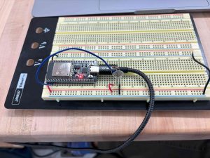
I was able to set up force-sensing resistors and read values from them on an ESP32.  Characterizing relationship between voltage and force might require some data collection, since the vendor documentation is somewhat lacking. This took longer than expected because of difficulties in finding the right toolchain for flashing my code to the ESP32. I ended up using Arduino IDE, but I would like to set up the ESP-IDF library and toolchain at some point.

I also completed the software for sending position commands to the stepper motors and wired up the stepper motors and demo these commands. The choice to use 3D printer driver boards really sped up the whole process compared to using individual motor drivers: all I needed to do was plug in the motors and send Gcode commands over serial .The power supply arrived, but the casing was damaged so I was not sure if it was safe to use since the casing is metal. However, I was able to overcome this by susbstituting the power supply module with a laptop charger.

My goal next week would be to finish building the XY axes of the gantry, including 3D printed parts. I am also aiming to build a prototype gripper mechanism.

See the stepper motor setup here:

https://drive.google.com/file/d/1oAM67E24leO2Pc1g6S6h67MTfPZt7vkb/view?usp=sharing

ESP32 setup:


Leland’s Status Report for 10/26/2024

This week, I followed the directions from this GitHub repository to download the necessary eYs3D libraries, but also some nice wrapper functions. After that, I was able to run a video demo of the depth map and the normal frames. The GitHub repository included these demos to test and calibrate the camera. Here is a link to my work document for this week.

Unfortunately, my progress is not on schedule. I wanted to include the ArUco tag calculation this week, but I wasn’t able to get that done. I have developed a schedule of my total workload for the next coming weeks. This will help me keep up with my other classes and free up time to spend towards this project. This is included in my work document. Despite being behind on schedule, I’m proud of my work this week. I had a lot of other hard class assignments to complete this week, and I got those done. I’m convinced that if I keep up this pace, we’ll be back on track by next week.

I have my deliverables for next week in my work document, but I will reiterate them here. By next week, I hope to write my own python script that utilizes the software packages I downloaded. This script needs to be able to identify and locate ArUco tags. I need the relative XYZ position of the tags and their orientation.

Team Status Report for 10/20/2024

Over the fall break, our team has worked in preparation of our parts being delivered. Which as of now, we have submitted all the orders for the parts we know we need. We have continued to research and implement the necessary software packages such that we can build our systems quickly when our hardware parts arrive.

The biggest risk right now is running into too many problems when parts arrive and we start putting together our prototypes. We have tried to mitigate this risk by spending our time preparing the software needed to control the system before and over the fall break.

The only change that was made this week was a 3D printer driver board that was acquired to replace the four separate driver boards. Jack made this change which he mentioned in his status report for this week.

Part A: Our system does include global factors. Part of the purpose of our project is to provide chemists with a safer environment to perform in a chemistry lab. Ideally, our system can be used anywhere in the world where one wishes to perform chemistry. Thus, it can keep people safer anywhere around the globe.

Part B: The Third Hand project could possibly have a cultural factor related to worker safety laws. Our product is designed to increase worker safety in chemistry lab environments. Thus, our team must consider the workplace safety requirements in the United States and how it will relate to our robot. Also, we should consider changing our testing strategy to better highlight our robot’s contribution to the safety in chemistry labs.

Part C: The Third Hand could have a environmental factor that should be considered. It is possible to have accidental spills that could leak toxic chemicals in the lab. Chemicals could spill down a drain contaminating the water, or evaporate and pollute the air. Our robot can be used in tandem with a proper work environment for it to prevent spills to harm individuals or the environment.

Leland’s Status Report for 10/20/2024

This week I started setting up the software environment to use the eYs3D stereo camera. I have created a Linux workspace on Ubuntu to run the image processing. Also, I have found the necessary SDK (Software Development Kit) to digitally capture frames. In combination of these two, I was able to produce some code that will capture frames with the SDK and convert them to a OpenCV matrix for further image processing. Here is a link to that code snippet.

Overall, I’m still on track for further camera calibration and ArUco marker detection for next week. For next week’s deliverables, I hope to be able to produce some visual examples of capturing and processing the camera frames. Also, I’d like to implement a code example that captures position and orientation of ArUco markers.

Cary’s Status Report 10/20/2024

Accomplishments This Week: This week, I successfully submitted all of my purchase orders and completed the design report with my team. However, due to traveling during fall break, I wasn’t able to accomplish much beyond these tasks.

Progress Evaluation: Although the purchase orders have been submitted, the TAs raised some questions, and the orders haven’t been placed yet. I expect these concerns to be resolved on Monday, after which the progress should return to normal.

Next Week’s Deliverables: Once the orders are placed, I plan to begin building the actual controller and assembling the components as scheduled. I really wants to get the orders through so we can actually starts to build the whole system,

Jack’s Status Report 10/20/2024

I was able to finalize the BOM for the robotic arm and order parts. Currently waiting for parts to arrive. In the process of finalizing the BOM, I made a decision to use a single 3D printer driver board instead of 4 stepper motor driver boards separately. This choice enables us to zero the stepper motors using built in current sensing. Furthermore, it will simplify the robotic arm software because I can send Gcode commands in the form of XYZ coordinates over UART to move the motors. This way, I no longer have to do PWM in software simulaneously over 4 channels and also keep track of the motor position myself.

I also got some software work done: I wrote some skeleton code for sending Gcode commads over UART to the robot arm. As soon as I get back to campus from fall break, I can start assembling the robot and start trying to deploy the exisitng parts of the software stack.

Team Status Report for 10/5/2024

The most significant risk to the project at the moment is not being able to build the prototype on time. The mechanical aspects of this project have been more challenging than anticipated. As a result, we could not finish the mechanical design as soon as we would have liked. The contingency plan right now is to have a meeting tomorrow to figure out what aspects of the system we have finalized and try to order parts for those aspects, so that we can get some subsystems out ASAP.

Another risk is that we build the force sensing/feedback protype, and the user experience is not as intuitive as we had wanted. We have looked into previous research and found that the most common solution approach for force feedback is to use haptic engines that could direct haptic feedback to specific parts of the user’s hand. However, such hardware is out of reach in terms of budget. The best way we can mitigate this is to build the remote controller prototype as soon as we can so that we have time to iterate.

In terms of design changes, we realized that ARUCO tags will not provide sufficient depth precision. We estimated depth precision to be ~7mm based on the tag’s size and the pixel resolution. Therefore, we switched from a monocular web cam to a binocular stereo cam to measure depth directly as opposed to via ARUCO tags. This will end up costing less because we are getting it from the 18-500 inventory, so it’s a win-win.

No schedule changes?

New cam!


Jack’s status report 10/5/2024

I have been working on designing the robot arm system in detail this week. I learned to use a new CAD program, Onshape, and it required a lot of effort. At the end, I was able to produce CAD drawing for multiple custom parts, and made good progress towards finishing the CAD assembly for the entire robot hand system. I also created the skeleton embedded code for controlling the robot arm. I wrote the code for sending PWM signal to interface with the motor drivers, as well as code to read measurements off force sensing resistors.

Progress Evaluation:

I am slightly behind schedule in terms of the mechanical components, as I should have already finalized the design at this point. However, I did get some software work done, which is what I was supposed to do this week.

Next Week Deliverables:

Complete CAD design for the robot. If the the parts arrive, also some parts assembly and wiring.


Onshape Assembly: