Bruce’s Status Report for 10.20

The first task I completed was finalizing the system implementation and testing plan in our design report. This is a crucial document that will guide the integration and verification processes for the project’s three core subsystems: the gantry system, vision system, and charging system. The plan outlines detailed steps for ensuring that each subsystem functions as expected and interacts seamlessly with the others. For instance, the testing plan includes scenarios that simulate real-world usage conditions, such as cases where the phone might be placed at varying orientations or positions on the table, or where the gantry system must make rapid adjustments. It also includes edge case testing, ensuring that the system can handle situations like multiple phones or objects being placed on the table simultaneously.

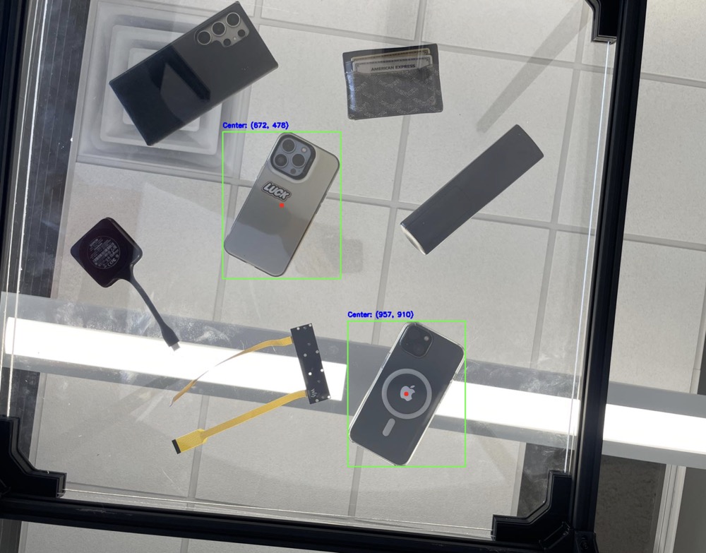
In parallel, I worked extensively on the computer vision system. Using the YOLO (You Only Look Once) object detection algorithm, I developed the first version of our vision system, which is capable of identifying the location of a phone on the table with an accuracy rate exceeding 90%. Since our parts have not arrived yet, I use my own camera to take pictures and detect the existence of the phone. In order to simulate the charging table situation, I intentionally make the phone face down, so the camera is taking pictures of the back of the phones.  The first version implementation ensures the system’s ability to detect phones reliably in most situations, which is essential for the proper functioning of the gantry system. The YOLO algorithm, known for its speed and precision in object detection, was trained on a custom dataset that reflects the specific conditions of our table—such as the camera angle, lighting conditions, and various phone models. I dedicated significant time to training the model and testing it against different cases to ensure accuracy, and the results so far have been very promising. The system is able to successfully detect phones in a variety of orientations and under different lighting conditions, which provides confidence in its real-world application. However, there is still room for optimization, particularly in reducing the time it takes for the system to process each frame and communicate the phone’s coordinates to the gantry system. It is also possible to improve the accuracy in some edge cases, such as when the light is not sufficient or too strong.

I have made several iterations of testing, refinement, and retraining to reach the desired accuracy level. I invested time in adjusting hyperparameters and improving the training dataset to enhance the system’s performance. Moreover, I spent time debugging certain cases where the system initially struggled to detect phones placed at extreme angles or partially obscured by other objects. These issues have largely been resolved, and I am confident that the system is now reliable enough for initial integration with the gantry system.

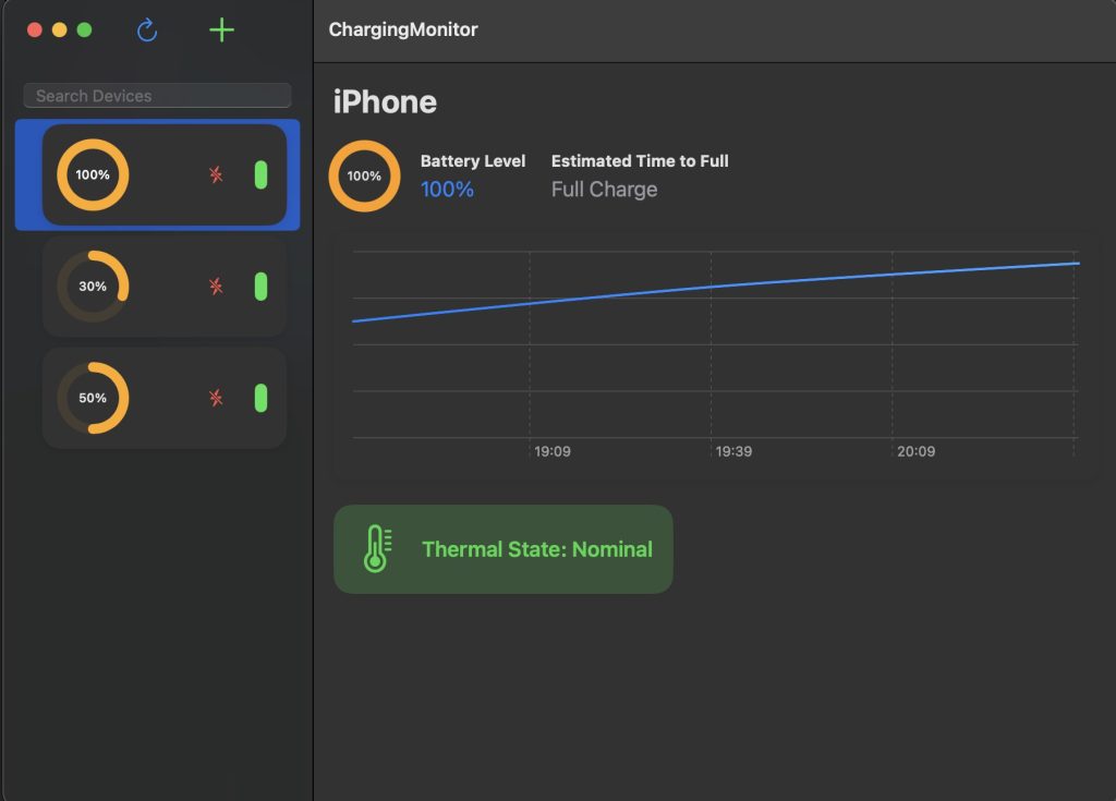
At this stage, I am happy to report that my progress is on schedule. The development of the vision system and completion of the design report are major milestones that were planned for this week, and I am confident that we are moving forward according to the timeline we established. The next step will be to begin the process of developing other systems as soon as our parts arrived. Also, I would continue to improve my algorithm for the vision system and continue developing the app for our smart charging table.

In terms of deliverables for next week, my focus will be on continue to develop the app we have right now.  Additionally, I plan to work on optimizing the vision system. While the system currently performs well, there are improvements that can be made in terms of speed and accuracy, particularly in handling more challenging scenarios like detecting phones in low light or at difficult angles. Reducing the latency of the system’s response is also a priority, as faster detection will allow the gantry system to move more quickly and efficiently.

Harry’s Status Report for 10.20

During the week prior to the fall break, we focused on our design review report for the project. I completed the use case/design requirements, design trade studies, and related work parts.  In the related work part, I looked into the team that has a similar project last year, discussed their problems and ways we could do better.  Some of these thoughts are reflected in the trade studies part because we modified our design several times to combine the gantry system and robot ideas.

Also, we received our central control unit: Nvidia Jetson Orin Nano. At the same time, we tested some basic circuits during the class time at Techspark. Also, we implemented some testing on the camera we have because we haven’t got the ordered camera yet. We looked into come basic implementation regarding image filtering and segmentation and we will continue to work on our original camera next week. After we got the Stereo Camera Nvidia Jetson Nano, we will compare these two devices and pick the one that is easier to program.

For me, this week I mainly familiarize myself with the Nvidia Jetson Orin Nano. There are detailed descriptions on Nvidia website regarding the ports names and usage. With my own keyboard and monitor, I’m able to connect the Jetson Nano with them using the DisplayPort connector. Then I was able to begin programming. At the same time, I gathered info about the gpio header pinout.

https://jetsonhacks.com/nvidia-jetson-orin-nano-gpio-header-pinout/

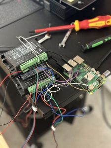
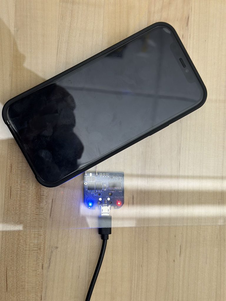
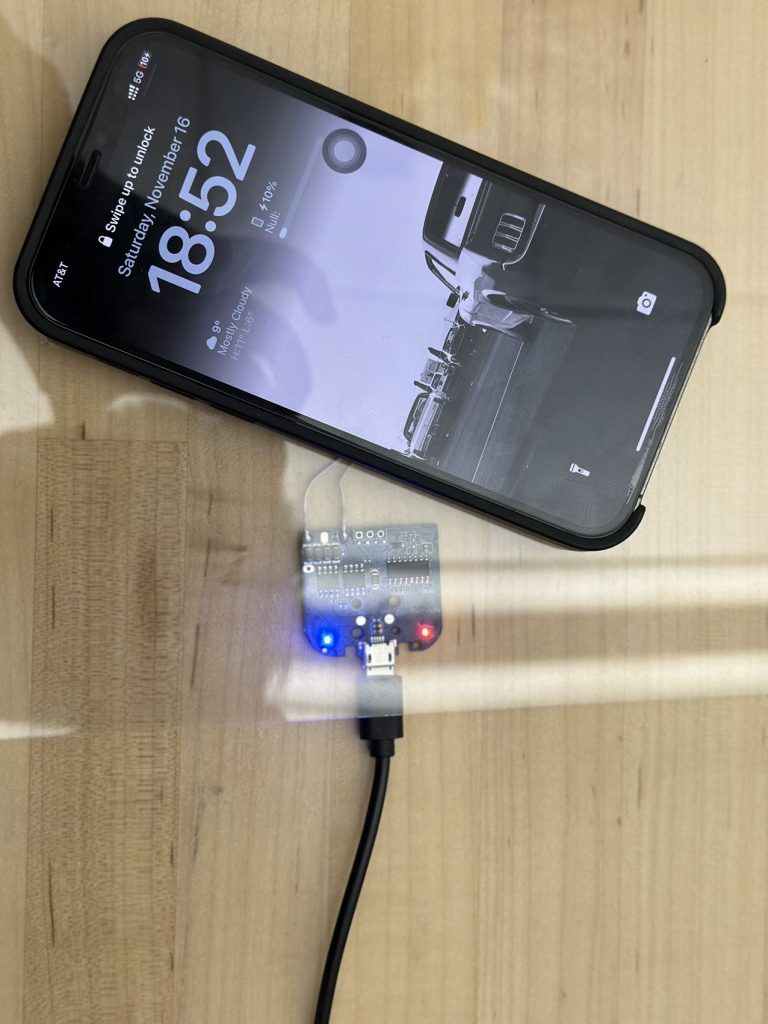
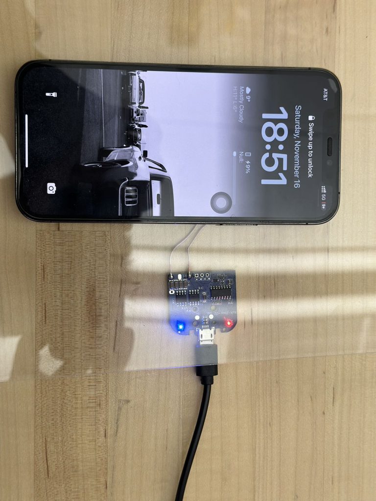
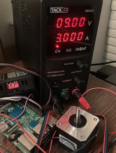
I followed this pinout to implemented some basic testings, for example use wires and breadboard to light up and LED, power a motor driver, etc. Also, this pins support UART, SPI as well as I2C communication protocols. I also test the existing camera with the Jetson Nano to complete some basic image filtering. It works now but I believe further testings should be implemented because this time I randomly take pictures. Detailed testing regarding taking pictures from the bottom to view the electronic devices on top of the table should be taken into consideration. We only confirmed there are transparent acrylic boards in Techspark but haven’t test them together with camera. I also dig into camera settings and found that environmental lights may also affect image filtering results, so we assume this table is placed indoor without too strong light from the top.

Overall, my progress is on schedule. During this week I begin to familiarize myself with Nvidia Jetson Nano and implemented some basic testings. Next week we will combine the Jetson Nano with components that will arrive. We will continue to develop the image filtering code with our existing camera. At the same time we will begin to construct the gantry system as well after receive the corresponding components.

Bruce’s Status Report for 10.5

This week, I took on the role of presenting the design introduction for our project. To ensure a smooth delivery, I thoroughly prepared my part, focusing on clearly conveying the main concepts and design rationale. I spent significant time rehearsing the presentation and refining the slides to make sure they were visually engaging and easy to follow. I also gathered feedback from my teammates during practice sessions to further improve the clarity and flow of the content.

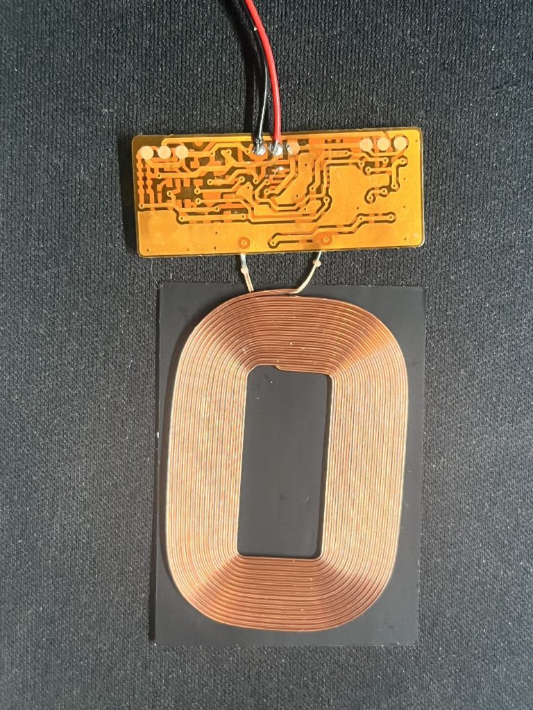
In addition, I was responsible for selecting the components for the charging pad module in our purchasing list. I researched extensively to determine the best options for our charging system, comparing various models and their specifications to ensure compatibility with our requirements. I also coordinated with my teammates to finalize other essential components, such as mechanical parts, ensuring our choices align well with the overall design and meet the project’s technical needs. This involved multiple discussions and iterations to balance cost, availability, and performance.

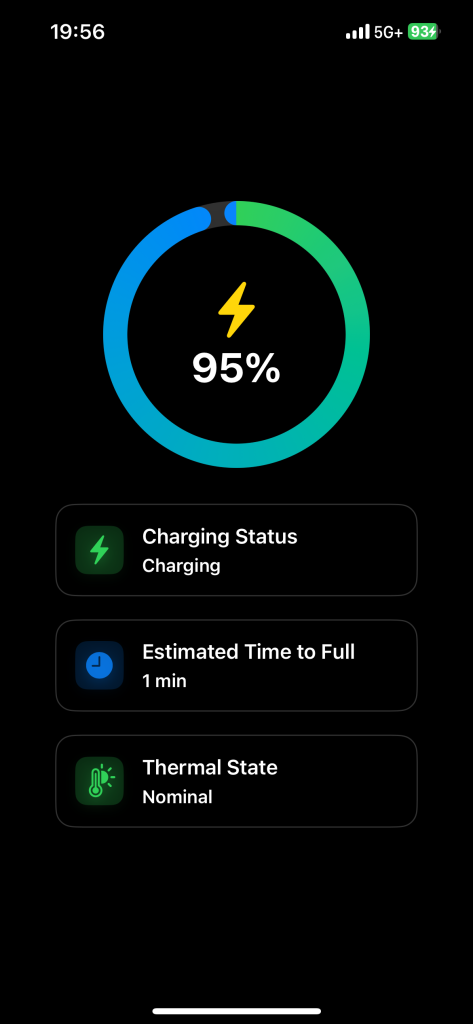
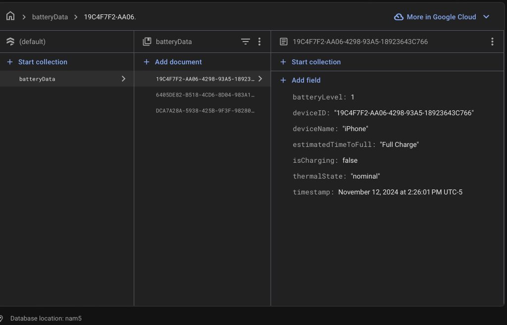
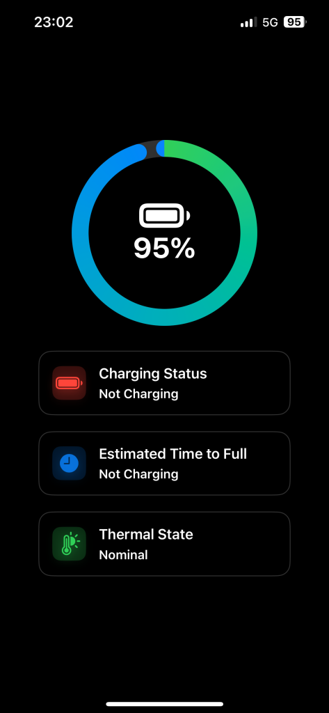
Lastly, I made improvements to the existing features of our app. I implemented a communication protocol that now allows the app to connect with other devices via WiFi, enabling real-time data exchange and expanding its functionality. Additionally, I started investigating the iPhone API to access information about temperature and charging status, which will further enhance the app’s capabilities. I looked through the API’s documentation and experimenting with different methods to retrieve the relevant data effectively. These improvements aim to make the app more user-friendly and provide more comprehensive information to users, preparing for our final design.


I am currently on schedule, and for the next steps:

  1. Finalize the purchase of the selected components and begin testing their integration into the system.
  2. Continue refining the app by completing the implementation of the iPhone API to gather temperature and charging status data, ensuring seamless integration.
  3. Work on the prototype of the charging pad module to verify its functionality and compatibility with the rest of the system.
  4. Collaborate with my teammates to set up a testing environment for the system, allowing us to identify any issues early and iterate on improvements.

Steven’s Status Report 10.5

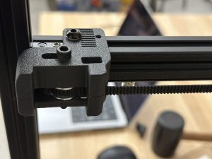
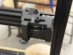
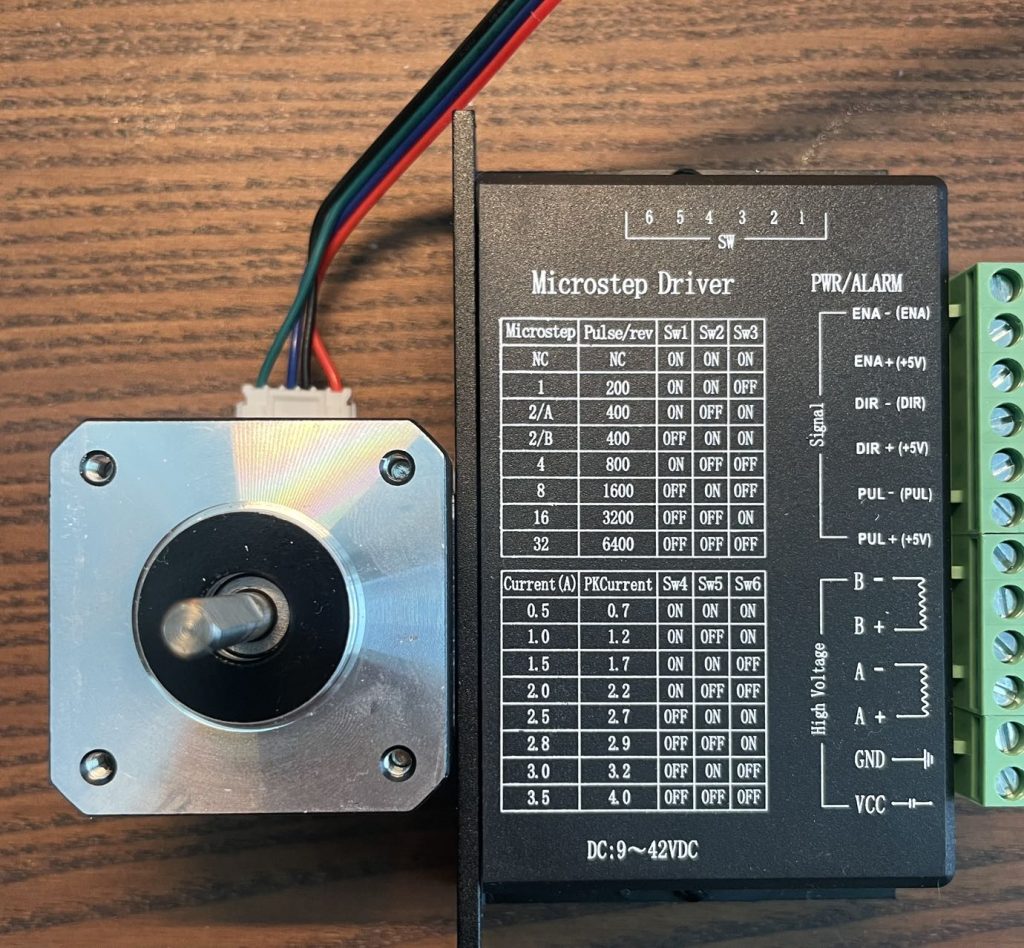
My first priority this week was to complete the mechanical modeling simulation and part selection for the Gantry system. For the power configuration, I chose a common NEMA motor to power the system, a set of two motors to power the horizontal and vertical movement of the entire system, and a separate motor to control the arm up and down to grab the charging pads for movement. Since I hadn’t touched or designed a gantry system before, I researched and borrowed some designs from cheaper 3D printers, and used a combination of two sets of moving and fixed pulleys and 6mm belts for the drive, as well as a set of MGN9 rails for the limit. I finished picking and filling out the drivetrain parts on the purchase list and we’ve submitted it to the TA for review. Since most of the parts are being purchased using Amazon, we hope to complete the development of the motor controller drives and the basic Gantry build over fall break and the following week.

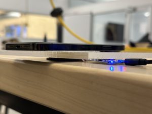
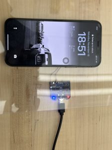
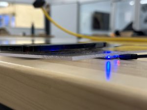
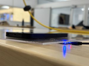
In the meantime, since we’re picking parts together this week, we think that choosing how thick the acrylic or glass panels will be is an essential thing to consider. We experimented with both 3mm and 5mm acrylic sheets and found that 3mm would be a good balance of strength and charging performance. We will use Techspark’s acrylic boards for the time being in subsequent experiments because of the possibility that the glass may break during the experiments. While waiting for the hardware to arrive, I also plan to finish testing the vision system with the team, and we will decide soon whether to use traditional vision or a machine learning model such as YOLO for cell phone device tracking. If machine learning is to be used for cell phone device tracking, we will immediately start collecting case data from cell phone devices and begin developing our first version of the model.


Team Status Report for 10.05

This week we focus on the implementation plan and system specification.

For the implementation plan, we research on the components we can borrow, want to buy, and need to develop.

We created a document list regarding the stuff we intend to purchase including linear rails that define the frame of the system. We also sorted out the types of motors, motor drives, belts, and rail sets that ensure 3D space motion.  We also research charging pad design and Qi-certified charging modules. We will first use the wireless charging pad from Apple official for current charging tests, but we will also start our charging pad prototyping recently as it is also a major component of our system design. We have done some research into the Qi protocol and module, and we have decided to monitor the charging progress on a software level to reduce complexity, so we don’t really need a complex charging pad design.

Also, we carefully look into the system specification for our detailed system design layout. Apart from the existing CAD design including the table frames, table layers, gantry system, and the camera system, we look into the wiring design layout of our system. We intend to ensure that the four charging pads can operate separately without colliding with each other. Also, their wires will not twist with each other. We also looked into the way we place the Jetson Nano and motor drivers, They will not affect the motion of our gantry system as well as the view of the camera. Last but not least, we want to implement some camera testing plans next week together with some transparent acrylic boards from TechSpark. We have done some research how to use the vision system to detect the mobile devices that need to be charged. There is a traditional and a machine learning approach. We will have the two prototype models done when returning from fall break and test their performance to decide which way we shall go. We will use the acrylic desktop for current testings as glass could be subject to break. We tested last week for the testing performance on a 3mm and a 5mm acrylic, it seems a 3mm desktop could be a nice choice for supporting the weight while doesn’t influencing the charging performance.

Overall, till now, the most difficult part we believe is the gantry system, The accuracy is very important. Because we will use the gantry system to move the charging pads around using a magnetic field, we need to ensure the system can successfully move the charging pads to very precise positions. Further tests will be implemented after rail sets for the gantry system parts arrive.

Harry Status Report for 10.05

Followed the finalized implementation plan to sort out the basic components we need. For example, in order to construct the table, we decided to purchase 12 pieces 600mm Aluminum Extrusion European Standard Anodized Linear Rail from Amazon. This rails will serve as the basic frame of our system. Apart from the rails, we together decided to purchase 3 NEMA17  motors,  2 stepper motor driver, long belts, and rail set that magnetic platform movement in x,y,z directions.

At the same time, I work together with teammates to look into the detailed design layout of our system. Because our system contains a lot of components, we need detailed layout design, especially for the charging pads. Because each charging pad is responsible for 1/4 section of the table, we will have wires connected to them from the four corners of the table. In this way, the charging pads will not affect each others’ motion and their wires will not twist with each other. We also did some research regarding how to place our Jetson Nano as well as wires that control the gantry system, making sure the wires will not affect our detection and motion system. Test and research on the camera will be further tested in the future.

Overall, my progress in on schedule. We confirmed a lot of quantitative details regarding our mechanical, electrical and software design this week. Next week we will first double check our component list with Nathan, our TA, and submit first round of components by Wednesday. We have a detailed list with components name and corresponding links. I believe each of us work well and collaborate well.

Next week, we will begin to gather components. Apart from the components we will purchase, some other components can be directly obtained from ECE department such as the Nvidia Jetson nano, camera, etc. We are still looking into the camera type we want. At the same time, the wires, LEDs, transparent acrylic board can be directly find in Techspark. We will begin some basic testing after some important components arrive as soon as possible.

Team Status Report 9.28

Design Finalization

This week, our team finalized the design of the smart charging table system, the main change we have are:

  • Gantry System: We have chosen a gantry-based system to move the charging pad. Instead of physically attaching the charging pad to the gantry or a robotic arm, the pad is constantly powered and placed between two layers. The gantry system will employ magnetic forces to move the charging pad to the desired location beneath the device.The main reason we change from robots to gantry system and separate magnetic charging pad is because in this case we do not need to worry about the wiring issue. For robots, since we need to apply power to them, the powering wire would cause many troubles to robots, which would affect the accuracy of it, and our current design would eliminate such problem

CAD Model Development

A major milestone this week was the successful development of the CAD model for the entire system. This included:

  • Detailed CAD of the system: Showing how the whole system works.
  • Layering structure: Visualizing how the charging pad will be placed between the two layers while still enabling smooth movement via the gantry system.

The CAD model provides a clear representation of the mechanical design and will serve as a reference for building the physical prototype.

App Prototype Creation

We also developed a prototype of the mobile app that will interface with the charging table. The app includes:

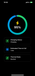
Charging status, device name, battery percentage, temperature, and estimated time to full charge.

The settings feature allows for future customization and functionality expansions. This prototype will be used for real-time communication between the table and users to ensure proper tracking of the charging process, and it will also serve as a feedback system.

Component List & Part Sourcing

We have also made progress on assembling the component list for the smart charging table:

  • Researched motors, sensors, and magnetic components that are suitable for the gantry system.
  • Explored charging pad options to ensure continuous power delivery while allowing movement within the system.
  • This work brings us closer to being ready for the procurement phase and building the first physical prototype.

Design Presentation

The team has also started working on a comprehensive design presentation as required, and finished most part of it.

The whole team is currently on schedule, and for our next week’s plan:

  • Continue refining the CAD model with detailed dimensions and tolerances.
  • Finalize the component list and begin sourcing parts for the physical build.
  • Begin working on the communication protocol between the app and the table hardware.
  • Try to prototype the charging pad model.
  • Improve on the App features.

Steven’s Status Report 9.28

This week in a meeting with my professor and TA we explored a technical challenge in our previous design, which was the question of how to power a movable rechargeable robot. We started with two solutions: one was to use wires to power the robots, however the tangling and resistance of the wires could cause a number of complications; the other was to add batteries to each of the robots, however after doing some research we realized that it would be difficult to charge the robots by homing them in place as the electrodes are too small and would place a huge demand on the robot’s controls and would be difficult to control. too large an electrode would pose problems such as circuit safety.

After several iterations this week, we finally decided to use a completely new design. We used the Gantry system, however, in order to achieve the effect of charging multiple devices at the same time, we came up with the innovative idea of using magnets on the end of the Gantry to move the charging pads across a layer of acrylic. This design is stable and efficient and allows for the charging of multiple devices.

After finalizing the design, I completed the mechanical design for the second version. This version focused more on the internal principles and concepts than the previous design, using real dimensions and an aluminum frame. This also meant that our design was being further refined. However, our Gantry system does not have the ability to purchase a frame directly due to its size, so we are still researching and discussing the design of this system. However the overall design is still very clear, and I have set deadlines for the complete overall design and hardware purchases that need to be made before fall break to ensure that our plans can continue to develop as we expect.

Bruce’s Status Report for 9.28

This week, I focused on creating a working prototype of the mobile app that will interface with our smart charging table. The app is designed to display essential information, including:

  • Charging Status (whether the device is charging or not)
  • Device Name (currently connected device)
  • Battery Percentage (real-time battery level)
  • Temperature (monitoring device temperature)
  • Estimated Time to Fully Charge
  • Settings (for customization and additional functionality)

The prototype was developed using HTML, CSS, and JavaScript, offering a sleek and intuitive user interface. The app will be the central communication tool between the table and the user, allowing real-time updates on charging status and other metrics. It will also serve as a feedback to the whole system, so that we know whether the phone is charged, and whether we need to adjust the charging pad position.

Coordination on Final Design

I had multiple discussions and feedback sessions with my teammates, and we finalized the core design of the system:

  • We are opting for a gantry system to move the charging pad to the desired location.
  • Instead of attaching the charging pad directly to the gantry or a robot arm, we decided to make the charging pad constantly powered. This pad is placed between two layers, and the gantry system will use magnetic forces to move it to the correct position for charging the device.
  • This approach reduces mechanical complexity and ensures constant power flow to the charging pad, making the system more reliable and efficient.

Component List and Part Sourcing

This week, I also started working on assembling the component list for our smart charging table. This involved:

  • Researching suitable parts for the gantry system, such as motors, magnetic components.
  • Evaluating charging pad technology that can be integrated seamlessly into the table and be constantly powered without overloading or power loss.
  • Ensuring that all components align with our design constraints, including size, power requirements, and budget.

Design Presentation

In addition to technical work, I began working on some parts of the design presentation slides. Some of the parts I worked on:

  • Overall concept and design goals.
  • The functionalities of the smart charging table, with visuals of the app interface and how it will communicate with the table.
  • A detailed explanation of how the gantry system and magnetic movement will work.

This presentation will help convey our design decisions and ensure that everyone is aligned as we move forward with implementation.

I am currently on schedule.

Next Steps:

  • Finalize the component list and begin buying parts.
  • Add more features to the APP.
  • Start implementing the communication between the app and the table’s hardware.

Harry Status Report for 9.28

Personal Work this week:

  1. Work on the design presentation, responsible for use case, quantitative design requirements, and solution approach parts.
  2. Proposed the idea of using armed robot (R robot, single arm) that could rotate. The charging station could then move forward and backward on the arm and finally reach desired charging position. In this condition, the wires and be placed inside the arm, successfully eliminate the original concern regarding the cubic robot’s (our original design) motion affected be charging wire. However, we think the limited area the end effector could reach and the precision issue caused by the arm robot will make our job extremely difficult. So we moved on.
  3. Meetings with teammates to review the design of our system. We went through in detail regarding our original design, which contains four cubic robots operating on the second layer of the system with each robot hold a charging pad (the charging pad is on top of the robot). However, one important fact that need to be taken into account is the way the robot and the charging pad is charged. Wireless charging can’t ensure constant power supply to the robot system; as for wired charging, the robot will drag the wire during the movement. In this condition, there will be great difficulty to prevent the wire from affecting the robot’s motion. Therefore, we worked together and decided to modify the design. In our new approach, between the second layer and the third layer will be a xy-axis motion system accomplished by belt (also consider linear motors, currently researching on some cheap options). as for the second layer, there will be four charging pads. The motion system (gantry) will use magnetic field to move the charging pad around. In that way we don’t need to worry about wire affecting the motion of the robot.
  4. Work on the component list. While some parts of the system can be directly produced using 3D printing, some other parts such as the layer, which will be either glass or transparent plastic, will be bought online. I have completed part of the component list and will continue to work on it.  We plan to use Nvidia Jetson nano instead of Raspberry Pi. Also, we are considering to build our own charging pad instead of directly purchase existing ones by creating magnetic field between the electronic devices and the charging station.  Qi-certified contract is being studied at the same time.
  5.  More details regarding the newest version of our design is included in team status report.

Overall, my progress in on schedule. Because we have finalized our design plan and begin to work on our component lists, we believe we are on the right track.

The next week, I will work together with my teammates for the component list. Because we have finalized our design, we are searching for corresponding components that matches with our design. At the same time,  I will work together with Steven to figure out the mechanical design of our system. Because now the second layer only contains the charging stations, the distance between layers will be modified. Also, we will continue to work on the presentation together to ensure our presentation can successfully illustrate and deliver our ideas.