Steven’s Status Report 12.07

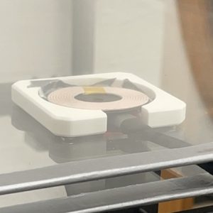
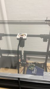
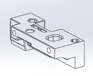
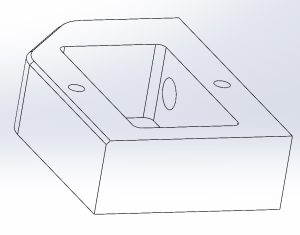
This week, our team successfully conducted the final presentation, effectively showcasing the significant advancements made in our hardware system. The presentation highlighted the structural improvements to the gantry system, particularly addressing the friction issues caused by the charging cable interacting with the charging pad connection. To resolve this, I enhanced our CAD model by increasing the distance between the glass interlayers on the tabletop by 2mm and redesigned the charging pad housing. These modifications ensure a better fit for the charging pad and prevent the cable from rubbing against the tabletop, thereby improving the system’s durability and performance.

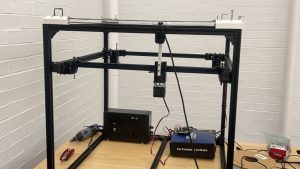
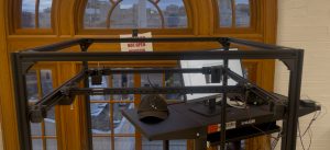
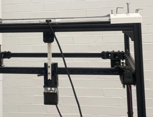
In addition to the structural enhancements, I dedicated considerable effort to unit testing and recalibrating the gantry subsystem. This involved fine-tuning the subsystem to accurately move specified distances in the XY direction and ensuring reliable interaction with the computer vision system. Moving from one end of the gantry system to another end, with 57 cm of travel distance, the average error rate for the system is about 1.8mm. We have also run several tests on Z axis manipulator and hardcode its value. Each time the travel distance of the Z axis has a 2-3mm error while trying to improve the stability, this margin of error is acceptable for the design.T hrough rigorous testing, we confirmed that the vision system accurately detects the coordinates of a cell phone and effectively directs the gantry to position the charging pad at the target location.

Looking ahead to next week, our focus will shift to further system integration and enhancing inter-system interactions. I will be collaborating with Bruce on state feedback detection and vision calibration for the gantry’s end effector, ensuring precise positioning after the charging pad is moved to its designated location. These efforts aim to refine the overall system functionality and ensure seamless operation across all components.

Overall, this week has been highly productive, with key improvements made to both the structural design and the functional integration of our gantry system. These advancements position us well for continued progress in the upcoming phases of the project.

Steven’s Weekly Status Report 11.30


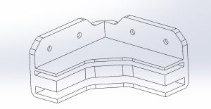
This week I continued to refine the hardware and control system for the gantry system. In order to ensure a close enough charging distance, I weighed the tradeoff between table thickness and charging effectiveness. Through testing, I found that a 3mm desktop ensures the best charging results i.e. charging with a case and without having to fully align the charging pad with the phone. However, the acrylic sheet we started with was not strong enough and its center section deformed very significantly and blocked the movement of the charging pad. On balance, I urgently purchased and cut glass panels and redesigned the CAD for the corner fixing parts, and tested to ensure that the charging pads would run silky smooth between the two layers of table tops, dragged by magnets.

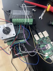
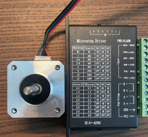
I also debugged the motor driver and wiring for the up and down movement of the manipulator to ensure that it could perform the specified movement and drag the charging pad under the table. After experimentation, the gantry system now moves the charging pad well. At the same time, because the motor wiring is more confusing. I organized its wiring and centralized the motor driver into a cardboard box to avoid it receiving disconnection and other problems. Next week I’m going to focus mainly on improvements in the accuracy and workload testing of the system as well as the smoothness of the integration.

As you designed, implemented, and debugged projects, what new tools or knowledge did you find you needed to learn to accomplish these tasks? What learning strategies did you use to acquire this new knowledge?

As an ECE student, I started with no specialized knowledge of gantry systems. I referenced many belt designs for 3D printers and other three-dimensional gantry units from the internet. At the same time, the motor driver was more complex than we thought. Since I had not used a stepper motor professionally before, it took me a lot of time to debug the PWM signals. I browsed through Arduino user forums and YouTube tutorials to properly match our motor driver with the motor body.At the same time, since the design process requires a lot of rework, I have also brushed up on a lot of skills such as Solidworks and 3D Printing Slicing through online tutorials and learning from my mechanical engineering friends to help us efficiently complete our tests and improvements.

Steven’s Status Report 11.16

Weekly Progress and Testing Plans

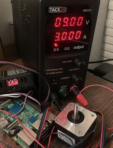
Harry and I spent about 30 hours this week building and testing the gantry system. We completed the hardware construction and testing of two sets of motor drives and belt drive systems. Currently, our motors can drive the manipulator to move smoothly. We encountered very many technical problems during the building process. First of all, our motor drive had the problem of insufficient torque at the beginning and could not drive the belt system during the actual system verification. I reduced the number of microsteps in the stepper motor drive from 6400 to 3200 and increased the drive voltage from 9V to 12V. We verified that this configuration could successfully drive the system by linking the motor to the belt and testing it with the whole gantry system.

We are still trying to test if we can control the end effector using the difference in speed and direction of rotation of the two motors because of a delay in the end effector part we 3D printed at Techspark.In the meantime, we have been verifying the charging of our wireless charging pads this week. We tested our 5W and 12W wireless charging modules as well as Apple’s original wireless charging module. The 12W charging module had the best results. We tested it on 3mm and 5mm acrylic boards, and with the 12W charging pad, we were able to charge a phone without a case on both thicknesses of acrylic boards very smoothly. For phones with cases, charging on 5mm acrylic requires a very tight fit between the phone and the charging pad. We will be printing out the charging plate pallets next week for the 5mm charging experiment to see if the 12W module can fully meet our needs. We plan to complete the gantry system to grab and release the charging pad next week and provide an API for the computer vision system to move the pad.

Team Weekly Status Report 11.09

One of the highlights for our group this week was the development and completion of the mechanical hardware for the automated charging table. Utilizing aluminum extrusions, we built a robust and reliable platform that supports data acquisition and machine vision training while ensuring the necessary strength and durability.

Along with hardware advances, substantial progress has been made in the gantry system, particularly in the integration and control of stepper motors. By integrating the motor drivers with the Jetson Orin Nano, the motor control code has been enhanced to greatly increase the functionality of the system. A prototype of the gantry system has been produced and the conversion between the step length of the stepper motor and the corresponding conveyor travel distance was successfully realized. In addition, the PID control algorithm was fine-tuned to improve the motor accuracy, reducing the margin of error to within 5 millimeters over a distance of 30 centimeters. While this level of accuracy meets our basic control requirements, we plan to make further adjustments to achieve even higher accuracy for more demanding tasks.

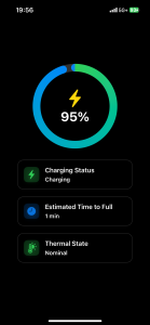
On the software side, we completed the design of the iPhone app, which now allows users to monitor the current state of charge, the estimated time to full charge, and the thermal state of the device. Future work will focus on integrating the app with web browsers and the macOS platform, allowing users to access device information while charging on their computers.

Looking ahead to next week, the plan is to mount the prototype gantry system to the main frame, using 3D printed parts to securely fasten components such as motors and belt gears. This step is critical to minimize vibration and ensure proper alignment during operation. Comprehensive performance tests will be performed on the assembled frame to assess the stability, accuracy and reliability of the system under real-world conditions. These tests will provide valuable insight into identifying sources of error and areas for improvement in the motor control algorithms and mechanics.

All in all, progress was made this week on both the mechanical and software portions of our project. The completion of the mechanical construction and enhancements to the gantry system’s motor controls have prepared us for the upcoming integration and testing phases. In the coming week, we plan to complete the overall construction of the system to ensure that the subsystems we designed in the mid-term demo are ready for basic functionality.

Steven’s Weekly Status Report 11.09

This week, my primary focus was assisting Harry in developing the overall framework of our project. Together, we dedicated a substantial amount of time to completing the mechanical hardware build for our automatic charging table. By utilizing aluminum extrusions, we were able to construct a sturdy and reliable platform that not only supports data acquisition an


d machine vision training but also maintains the necessary strength and durability required for our operations. The modular design facilitated by the aluminum extrusions allows for easy adjustments and future scalability, ensuring that our framework can adapt to evolving project needs.

In addition to the mechanical advancements, I made significant progress on the gantry system, particularly concerning the stepper motors. I enhanced the motor control code by integrating motor drivers with a Jetson Orin Nano, which improved the overall functionality of the system. A key achievement this week was the successful conversion between the step size of the stepper motors and the corresponding belt travel distanc


e. This was accomplished by constructing a simple prototype of the gantry system, which served as a proof of concept for our control mechanisms. Furthermore, I tuned a set of Proportional-Integral-Derivative (PID) controllers to achieve more precise motor control. As a result, the motors now operate with increased accuracy, maintaining an error

margin within 5 millimeters over a 30-centimeter distance. While this level of precision meets our basic control requirements, it highlights the need for further adjustments to the control program to achieve higher precision for more demanding tasks.

Looking ahead to next week, our plan involves mounting the gantry system prototype onto the main frame. This will require the use of 3D-printed parts to securely fix components such as the motors and belt gears. Ensuring that these components are firmly attached and properly aligned is crucial for minimizing vibrations and misalignments during operation. Once the prototype is mounted, we will conduct comprehensive performance tests on the actual frame to assess the system’s stability, accuracy, and reliability under real-world conditions. These tests will provide valuable data for identifying any sources of error and areas that need improvement in both the motor control algorithms and the mechanical setup.

Simultaneously, I will continue refining the motor control program to enhance precision further. This includes fine-tuning the PID parameters and exploring advanced control algorithms that can reduce the existing error margin. Additionally, integrating more sensors or feedback mechanisms may offer real-time data, allowing for more accurate adjustments and control. Maintaining effective communication with team members remains a priority to ensure cohesive progress across all project aspects. Efficient resource management, including the allocation of materials for the mechanical build and computational resources for code development, has been instrumental in our advancements this week.

In summary, this week has seen substantial progress in both the mechanical and software components of our project. The completion of the automatic charging table’s mechanical build and the advancements in the gantry system’s motor control have established a solid foundation for the upcoming integration and testing phases. Addressing the current precision challenges and continuing to refine the control algorithms will be essential in enhancing the overall performance and reliability of our system in the weeks to come.

Steven’s Status Report 11.02

This week, my main focus was motor development. I successfully configured the motors on the Raspberry Pi using an external power supply to be able to perform basic commands such as turn and stop. Given that the Nvidia Jetson Orin Nano utilizes the same GPIO libraries as the Raspberry Pi, we were able to extend the motor control functionality to the Jetson platform, facilitating seamless integration with the motor driver. This compatibility provides a streamlined path for us to continue development on Jetson.

Despite these advances, I still need to accelerate the completion of the gantry system. It is important that we complete this work as soon as possible because it will allow us to translate coordinate positions directly into motor commands. This capability is critical to achieving the precise motion control we need for our application.

On the assembly side, Harry and I collaborated on the 3D-printed parts of the gantry and have made significant progress in building the structure. Next week, we plan to complete the assembly of the gantry system for functional testing. This phase will involve validating and assembling the mechanical design and ensuring consistency with the motor control logic. It is important that we complete the build and commissioning of this system as soon as possible, as we have created a partial gap between our process and our plan.

In addition, since the motor is the only component in our system that requires a high voltage range of 15V to 45V, we must determine the best way to fully power it. Our main challenge was to find a power solution that could be centrally managed to ensure operational safety. This required selecting a power supply or battery management system that could interface with our controllers, allowing us to safely monitor and control the power supply to the motors.

Steven’s Status Report 10.26

Due to an unforeseen procurement issue, we were not able to obtain the aluminum profiles and motors and accessories needed to build our gantry system as planned this week, so we were not able to begin assembling our system. So this week I spent my time mostly on the parts that didn’t require physical hardware.

This week I further refined the CAD modeling and simulation, and following up on last week’s design of the motor support structure, this week our motors were able to be fixed in their designated positions and function properly in the type of environment we were working in. I fabricated the motor support structure at Roboclub using a 3D printer, however because of the slicing problem. Our parts were not able to reach the hardness we needed during testing, so next week we need to continue 3D printing to get a strong enough motor mount.


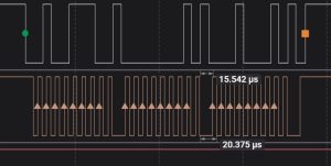
Carrying on from last week’s motor controller development, I wiring the Jetson Orin Nano this week, there was some difficulty with the pin assignments as we have more peripherals, however as the motor driver only needs analog signals we assigned it to a few free pins. It was tested by a logic analyzer and it works properly.

We have been notified of the arrival of our hardware this Friday afternoon, and next week we hope to finish connecting and debugging the motor controllers and attempt to begin building and debugging the gantry system.

Team Weekly Status Report 10.20

This week, our focus was on advancing multiple aspects of the smart charging table project, including both hardware and software developments, while ensuring that we remain on schedule. A key milestone was the finalization of our design review report, where each team member contributed significantly to different sections. For example, In the related work, we examined a previous team’s similar project, identified their challenges, and integrated improvements into our design. This reflection on prior work led to several modifications to our original design, particularly in how we will combine the gantry system with the robotic control ideas.

On the hardware side, we received and began working with the Nvidia Jetson Orin Nano, which will serve as the central control unit for our project. Our efforts this week were focused on familiarizing ourselves with its interface, setting up the initial programming environment, and conducting basic circuit tests in Techspark. We set up the Jetson Orin Nano using a DisplayPort connector with a keyboard and monitor, successfully gathering information about the GPIO header pinout from resources online. We used this pinout to test basic functionalities, such as powering an LED and a motor driver through breadboard circuits. We also explored communication protocols such as UART, SPI, and I2C, which will be critical for integrating various sensors and components moving forward.

In parallel, we continued testing the camera system, despite not yet receiving the stereo camera we ordered. Using the available camera, we implemented basic image filtering tests, simulating real-world conditions by positioning the camera to capture electronics on a table. We are still refining these tests, taking into account environmental factors like lighting and object positioning. Once the stereo camera arrives, we plan to compare its performance with the Nvidia Jetson Nano’s built-in camera to determine which setup is more efficient for our application.

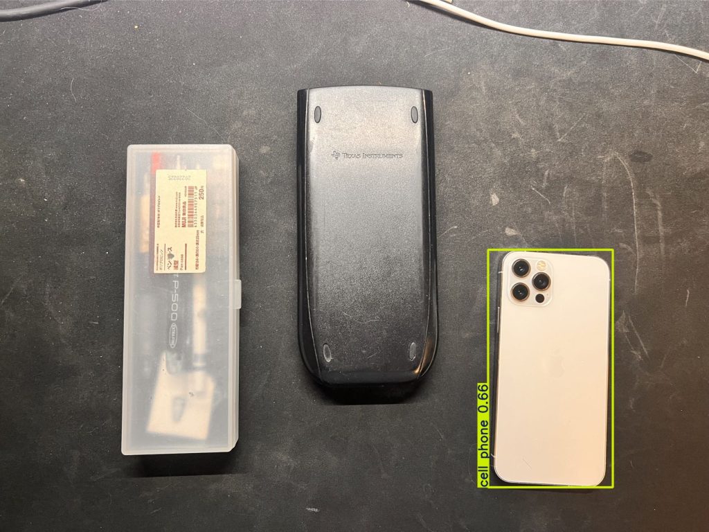
Regarding the vision system, we made significant progress by implementing the YOLO object detection algorithm. The first version of our system is now capable of detecting phones on the table with over 90% accuracy, even when the phone is facedown, simulating the real charging scenario. The algorithm was trained on a custom dataset to reflect the specific conditions we anticipate in real use, such as varied lighting and phone orientations. While this initial implementation is promising, We are working to further optimize the system by reducing latency and improving performance in edge cases, such as low light conditions or when the phone is obscured.
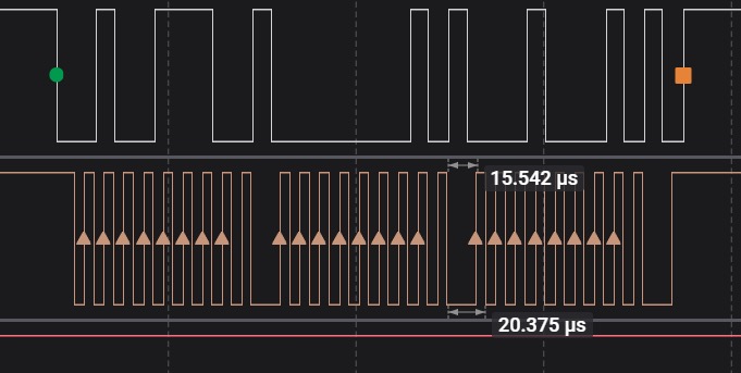
For the gantry system, we are developing the motor control system using TB6600 motor controllers. This week, we wrote the initial control code using the Jetson.GPIO library and successfully tested it on the Jetson Orin Nano. The next step is to integrate the motor controllers with the actual motors, once they arrive, and begin full power load testing with a second controller for more complex gantry operations.
Consideration of Global Factors
The smart charging table we are designing addresses a global need for efficient, multi-device wireless charging in a variety of settings, from personal homes to commercial spaces. With the growing number of mobile devices worldwide, especially in fast-growing markets, there is a clear need for versatile and reliable charging solutions that can cater to different phone models and device types. Our system, leveraging the Nvidia Jetson Orin Nano’s processing power and the precision of our gantry system, is capable of identifying and charging multiple devices simultaneously and automatically, making it applicable to global consumers who demand flexibility and efficiency in their device management. By designing a system that can adapt to varying environmental conditions and device types, we are catering to a broad audience beyond just technologically advanced or academic environments. What’s more, our product is fully automatic, which ensures that the system can be deployed in any region, helping users efficiently manage their devices without requiring advanced technical knowledge.

Consideration of Cultural Factors
Our product design takes into account the diverse ways in which people across different cultures use and interact with technology. For example, in regions where multiple device ownership is common, our system’s ability to detect and charge several devices at once offers a significant advantage. We have also considered user interface design, ensuring that the system is intuitive and easy to use for people with varying levels of technological expertise. The seamless operation of our gantry and vision systems ensures that the system can be used by anyone, regardless of their background or experience with similar products. Additionally, we have taken care to ensure that the design is adaptable to different environments and cultural contexts, whether it is being used in a high-tech office or a traditional household. Lastly, our software is going to support multiple languages, which would make people that do not understand English use the product easily.

Consideration of Environmental Factors
Our design incorporates environmental sustainability by focusing on energy efficiency and reducing material waste. The gantry system has been optimized to minimize power consumption without sacrificing performance, and the use of 3D-printed components allows us to limit material waste during production. Moreover, by encouraging users to centralize their device charging in one place, we are promoting more efficient energy usage compared to having multiple chargers in various locations. The smart charging table’s longevity and adaptability also reduce electronic waste, as the system is designed for durability and can accommodate future technology updates, extending its usable life. These considerations ensure that our system is not only practical and efficient but also environmentally responsible.

(A was written by Steven Zhang, B was written by Bruce Cheng, C was written by Harry Huang)
Steven’s Weekly Status Report 10.20

This week my work has been focused on following up on the progress of parts procurement and driver development for the motor controllers. I worked on the TB6600, a motor controller. My current design is to connect the + and – terminals of the motor controller to the motor and use the Jetson GPIOs to connect the Pulse, Direction, and Enable terminals of the controller and then use the Jetson.GPIO library to control the motor controller. This week I finished writing the original code and successfully ran it on the Jetson. I used a digital logic analyzer to analyze the waveforms of the GPIO pins to make sure they were working properly. Next week when the controllers and motors arrive, I will start working on the hardware connections to actually use the Jetson to control the motors and add a second controller for full power load experiments.

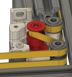
Meanwhile, this week I’ve been working on the precision design of the mechanical hardware. I designed some 3D printed parts such as supports to hold motors and fixed and moving pulleys for the gantry system. We plan to start 3D printing parts next week to ensure the mechanical stability and viability of the whole system.

We submitted our purchase request two weeks ago, and since most of our purchases come from Amazon, I expect that we should receive most of our parts next week. Next week we will be working on building and field testing the hardware. I plan to spend some time completing the aluminum frame build and basic experimentation with the gantry system.

Steven’s Status Report 10.5

My first priority this week was to complete the mechanical modeling simulation and part selection for the Gantry system. For the power configuration, I chose a common NEMA motor to power the system, a set of two motors to power the horizontal and vertical movement of the entire system, and a separate motor to control the arm up and down to grab the charging pads for movement. Since I hadn’t touched or designed a gantry system before, I researched and borrowed some designs from cheaper 3D printers, and used a combination of two sets of moving and fixed pulleys and 6mm belts for the drive, as well as a set of MGN9 rails for the limit. I finished picking and filling out the drivetrain parts on the purchase list and we’ve submitted it to the TA for review. Since most of the parts are being purchased using Amazon, we hope to complete the development of the motor controller drives and the basic Gantry build over fall break and the following week.

In the meantime, since we’re picking parts together this week, we think that choosing how thick the acrylic or glass panels will be is an essential thing to consider. We experimented with both 3mm and 5mm acrylic sheets and found that 3mm would be a good balance of strength and charging performance. We will use Techspark’s acrylic boards for the time being in subsequent experiments because of the possibility that the glass may break during the experiments. While waiting for the hardware to arrive, I also plan to finish testing the vision system with the team, and we will decide soon whether to use traditional vision or a machine learning model such as YOLO for cell phone device tracking. If machine learning is to be used for cell phone device tracking, we will immediately start collecting case data from cell phone devices and begin developing our first version of the model.