Team Status Report for 10.05

This week we focus on the implementation plan and system specification.

For the implementation plan, we research on the components we can borrow, want to buy, and need to develop.

We created a document list regarding the stuff we intend to purchase including linear rails that define the frame of the system. We also sorted out the types of motors, motor drives, belts, and rail sets that ensure 3D space motion.  We also research charging pad design and Qi-certified charging modules. We will first use the wireless charging pad from Apple official for current charging tests, but we will also start our charging pad prototyping recently as it is also a major component of our system design. We have done some research into the Qi protocol and module, and we have decided to monitor the charging progress on a software level to reduce complexity, so we don’t really need a complex charging pad design.

Also, we carefully look into the system specification for our detailed system design layout. Apart from the existing CAD design including the table frames, table layers, gantry system, and the camera system, we look into the wiring design layout of our system. We intend to ensure that the four charging pads can operate separately without colliding with each other. Also, their wires will not twist with each other. We also looked into the way we place the Jetson Nano and motor drivers, They will not affect the motion of our gantry system as well as the view of the camera. Last but not least, we want to implement some camera testing plans next week together with some transparent acrylic boards from TechSpark. We have done some research how to use the vision system to detect the mobile devices that need to be charged. There is a traditional and a machine learning approach. We will have the two prototype models done when returning from fall break and test their performance to decide which way we shall go. We will use the acrylic desktop for current testings as glass could be subject to break. We tested last week for the testing performance on a 3mm and a 5mm acrylic, it seems a 3mm desktop could be a nice choice for supporting the weight while doesn’t influencing the charging performance.

Overall, till now, the most difficult part we believe is the gantry system, The accuracy is very important. Because we will use the gantry system to move the charging pads around using a magnetic field, we need to ensure the system can successfully move the charging pads to very precise positions. Further tests will be implemented after rail sets for the gantry system parts arrive.
Harry Status Report for 10.05

Followed the finalized implementation plan to sort out the basic components we need. For example, in order to construct the table, we decided to purchase 12 pieces 600mm Aluminum Extrusion European Standard Anodized Linear Rail from Amazon. This rails will serve as the basic frame of our system. Apart from the rails, we together decided to purchase 3 NEMA17  motors,  2 stepper motor driver, long belts, and rail set that magnetic platform movement in x,y,z directions.

At the same time, I work together with teammates to look into the detailed design layout of our system. Because our system contains a lot of components, we need detailed layout design, especially for the charging pads. Because each charging pad is responsible for 1/4 section of the table, we will have wires connected to them from the four corners of the table. In this way, the charging pads will not affect each others’ motion and their wires will not twist with each other. We also did some research regarding how to place our Jetson Nano as well as wires that control the gantry system, making sure the wires will not affect our detection and motion system. Test and research on the camera will be further tested in the future.

Overall, my progress in on schedule. We confirmed a lot of quantitative details regarding our mechanical, electrical and software design this week. Next week we will first double check our component list with Nathan, our TA, and submit first round of components by Wednesday. We have a detailed list with components name and corresponding links. I believe each of us work well and collaborate well.

Next week, we will begin to gather components. Apart from the components we will purchase, some other components can be directly obtained from ECE department such as the Nvidia Jetson nano, camera, etc. We are still looking into the camera type we want. At the same time, the wires, LEDs, transparent acrylic board can be directly find in Techspark. We will begin some basic testing after some important components arrive as soon as possible.

Harry Status Report for 9.28

Personal Work this week:

  1. Work on the design presentation, responsible for use case, quantitative design requirements, and solution approach parts.
  2. Proposed the idea of using armed robot (R robot, single arm) that could rotate. The charging station could then move forward and backward on the arm and finally reach desired charging position. In this condition, the wires and be placed inside the arm, successfully eliminate the original concern regarding the cubic robot’s (our original design) motion affected be charging wire. However, we think the limited area the end effector could reach and the precision issue caused by the arm robot will make our job extremely difficult. So we moved on.
  3. Meetings with teammates to review the design of our system. We went through in detail regarding our original design, which contains four cubic robots operating on the second layer of the system with each robot hold a charging pad (the charging pad is on top of the robot). However, one important fact that need to be taken into account is the way the robot and the charging pad is charged. Wireless charging can’t ensure constant power supply to the robot system; as for wired charging, the robot will drag the wire during the movement. In this condition, there will be great difficulty to prevent the wire from affecting the robot’s motion. Therefore, we worked together and decided to modify the design. In our new approach, between the second layer and the third layer will be a xy-axis motion system accomplished by belt (also consider linear motors, currently researching on some cheap options). as for the second layer, there will be four charging pads. The motion system (gantry) will use magnetic field to move the charging pad around. In that way we don’t need to worry about wire affecting the motion of the robot.
  4. Work on the component list. While some parts of the system can be directly produced using 3D printing, some other parts such as the layer, which will be either glass or transparent plastic, will be bought online. I have completed part of the component list and will continue to work on it.  We plan to use Nvidia Jetson nano instead of Raspberry Pi. Also, we are considering to build our own charging pad instead of directly purchase existing ones by creating magnetic field between the electronic devices and the charging station.  Qi-certified contract is being studied at the same time.
  5.  More details regarding the newest version of our design is included in team status report.

Overall, my progress in on schedule. Because we have finalized our design plan and begin to work on our component lists, we believe we are on the right track.

The next week, I will work together with my teammates for the component list. Because we have finalized our design, we are searching for corresponding components that matches with our design. At the same time,  I will work together with Steven to figure out the mechanical design of our system. Because now the second layer only contains the charging stations, the distance between layers will be modified. Also, we will continue to work on the presentation together to ensure our presentation can successfully illustrate and deliver our ideas.

Harry Status Report 9.21

During Wednesday, we presented our idea and proposal to the whole class to demonstrate our project: AutoChargerX. As the presenter, I carefully practiced to ensure that my presentation will be clear, insightful and easy to understand. At the same time, I dig into some specific design part of our project to make sure I can answer questions raised by professors, TAs, and other students.

Because the presentation is divided into many separate parts, we my teammates and I prepare for the presentation, we first divided the work between us thus each of us were responsible for several parts. After everybody finish his work, we then combined our work together.

My parts include use case introduction, use case requirements, part of technical challenges and the MVP definitions. I searched online for a variety of resources and listed some common problems for today’s charging systems. I pointed out that an automated wireless charging system will greatly help people with their everyday life because a home based wireless charging table can offer then convenience and high efficiency.

I also communicated with my teammates and drew out the brief design layout of our table system as shown below:

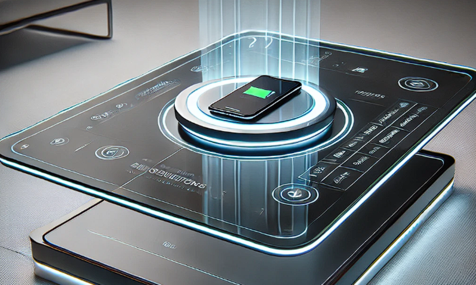
The three layered table system contains the surface, robot operating platform and the camera hub. The robot will hold the charging pads, which are on top of the robots and pair with the electronic devices on the surface of the table. The camera on the third layer will monitor the whole system and send feedbacks to control software, robots, and other devices in the system.

For MVP, I discussed from several viewpoints: table system, wireless charging module, automated device detection and alignment, robot motion plan, and feedback control software. In MVP, the numerical requirements are not as strict as those we mentioned for our final target because we want to make everything work first then try to reach higher efficiency.

Next week, we will further discuss our design with the professors and listen to their advice.


Introduction and Project Summary

In the modern era, smartphones and wireless devices have become indispensable to daily life. However, the process of charging these devices remains cumbersome. Wired charging requires physical effort and proximity to a power source, often forcing users to get out of bed or remain tethered to a specific spot. On the other hand, wireless charging, though more convenient, requires precise placement of the device on a charging pad. Even a slight deviation from the center can prevent the device from charging, leading to frustration and potential battery depletion when the user expects a full charge.

The need for a more user-friendly charging solution has become evident. A smart charging table can address these challenges by combining the convenience of wireless charging with the accuracy of automated positioning. By incorporating innovative technology that autonomously locates and aligns with devices, this table aims to revolutionize the charging experience, providing a seamless, efficient, and hands-free solution.

For our project, we will to design a smart charging table that can be placed in public areas such as libraries to help people with their charging issues. The table will have two layers: a transparent desktop on top and a charging system on the second layer beneath the desktop. The charging system will contain components that first automatically detect the position of your electronic device, such as your phone, and then move a magnetic charger to the position right below your phone and begin charging. During the whole process, the only thing you need to do is to place your phone on the table, and our device will do all the work automatically.