Harry’s Status Report for 12.07

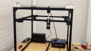
Based on our final presentation, the remaining for us contains software (gantry system tracking, alignment feedback control) and hardware (workload test and cable management)

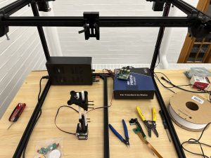
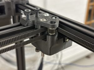
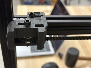
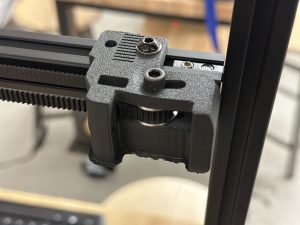
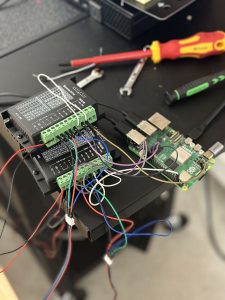
For the past week, after our presentation on Wednesday, we begin to test on charging pad alignment with the camera. The work I completed (primarily with Steven together for the hardware part) contains:

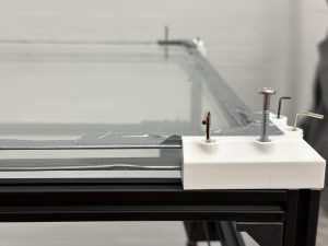
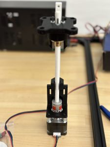
  1. Test original center manipulator. Use test code to let center manipulator drag the charging pad. However this configuration is not stable: sometimes can’t successfully drag; center manipulator very unstable with PLA shaft and rail. We tested for around 20 times, and around 8 times the center manipulator can’t successfully drag around the charging pad with wire. Therefore, we intend to modify the material of the center manipulator, the design of corner fasteners as well as the charging pads.
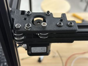
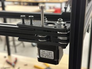
  2. Change to steel rail and shaft. Change screwing methods. Fix the shaft and rail right to the center manipulator. These changes are made to ensure the center manipulator is very stable and can successfully drag the charging pad.
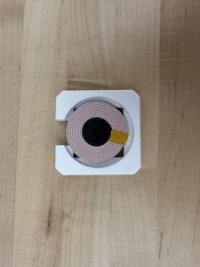
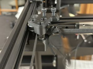
  3. Help with corner fastener redesign and charging pad structure redesign.
  4. Help with software integration tests. Camera detect phone –> gantry move charging pad to the position of the phone –> start charging. Still tuning
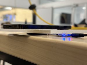
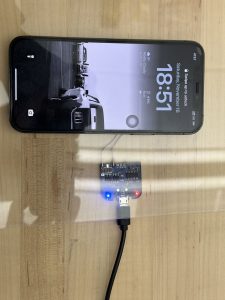
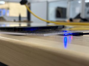
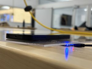
  5. We increased the distance between the two glass boards. Increased the height of the charging pad. This makes sure the type C wire does not come out the charging pad at the bottom. 20 trails were implemented and 18 trails completed. One fail trail the charging module was not fixed well to the charging pad. The other fail trail the manipulator failed to drag the charging pad.
  6. Fine tuning of the CV system was also implemented. We placed the camera at several different positions to ensure it can view the whole top of the table. Based on the fixed position of the camera, we record the position and begin to fine tune the movement of center manipulator. We transform pixel distance to real world distance and change input values for fine tuning,

Next week: Video, poster, final report ongoing. Overall on time. Still a lot of paper work to do.
Team Status Report for 11.30

Our most crucial work for the past week is described in subsections as below.

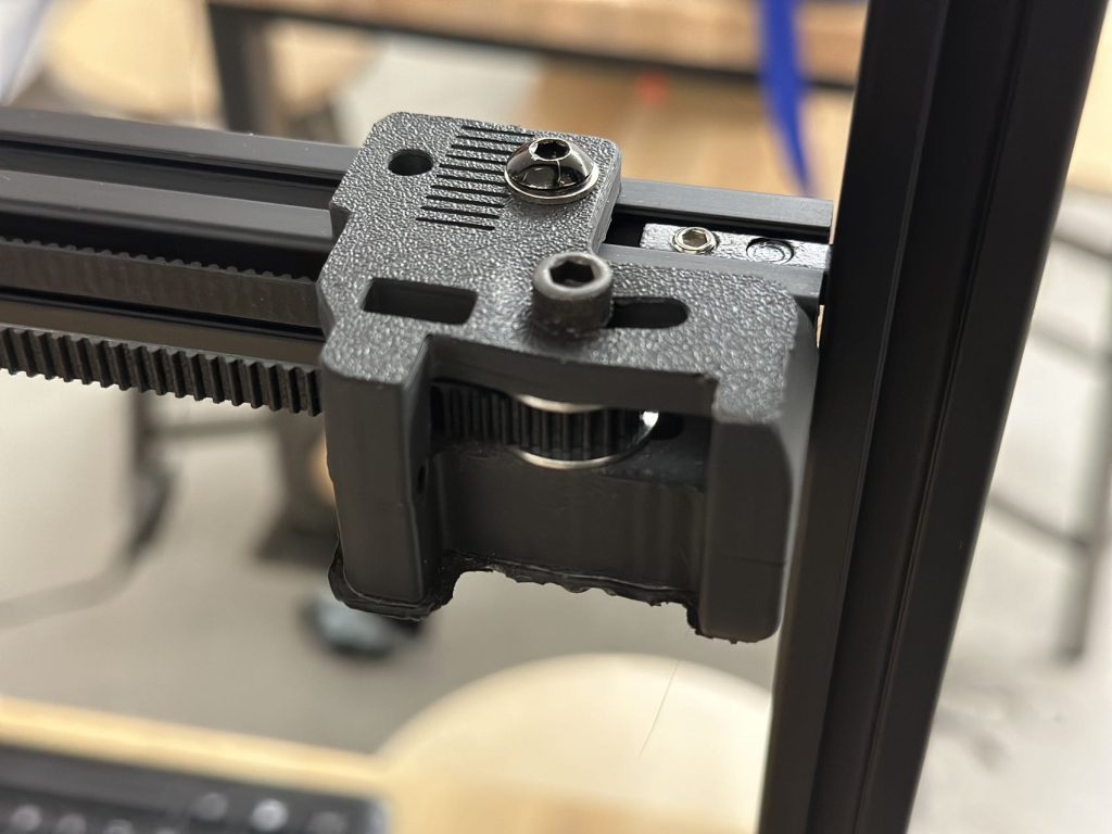
  1. Gantry system debug based on problem exhibited in interim demo:The problem that led to slow and uneven movement of the belt is the deformation of this 3d part. We reprinted this 3d part using ABS and it can then move on all x, y and z axis
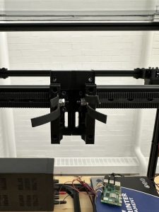
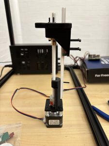
  2. Center manipulator can operate as intended. Center manipulator is attached to the manipulator on the center rail. Also shaft and rail are assembled for center part to move up and down
  3. Glass boards are used to replace acrylic boards to ensure minimal structure changes
  4. Code is updated for testing the whole gantry system
  5. Charging module and charging pads are redesigned.
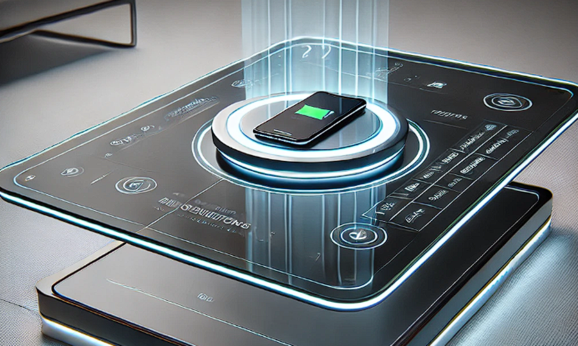
  6. Charging  success rate is ensured. Using around 2.6mm glass, the center manipulator can use magnets to attract the charging pad and move it around. Phone on top of the table can be successfully charged through testings. Video demos are taken and might be shown in presentation slides.

At present, the construction and testing of the overall hardware system has been completed, and more tests on intergation and workload are needed.

Harry’s Status Report for 11.30

The work I finished for the past week is described as below:

  1. Center part design/printing/purchasing/assemblyAssembled center part. Contains stepper motor, base, shaft, rail, upper part. The rail and the shaft are printed. Steel made rail and shaft are ready for cut (will be performed in machine shop). The upper part (primarily for charging pad attraction using magnets and movement) can move up and down on the shaft. Video was taken. This part is fixed onto the center manipulator as shown below: 
  2. Charging pad (charging pad was reprinted two times before it can work as intended) Steven will show in detail regarding charging results.
  3. Acrylic boards are replaced by glass boards and are fixed to the top of the table. Corners are reprinted to make sure they matches with the size of the glass board as well as the height of the charging pad
  4. Whole system overview with motor drivers fix into a box.Power supply under the table. All hardware parts completed. Assembled and tested for many times. Gantry runs good with odometry, can operate in all x, y and z axis. Center manipulator can drag charging pad around using magnets. 
  5. System integration already began. Camera control gantry movement. Bruce will update on this.

Tools and knowledge needed to accomplish these tasks:

  1. Mechanical design skills
  2. Understanding of Rpi programming logics (eg: gpio),
  3. Gantry system principles
  4. Testing and troubleshooting methods: hw, sw, meche, external force
  5. Quick 3d printing skills
  6. system integration skills, how to connect sw, hw and meche together. How to control the subsystems.

learning strategies

  1. Online documents blogs for Rpi use
  2. Online videos for specific motor driver use
  3. Rpi/Motor/Motor driver operational manual
  4. Consult other students, professors

We will continue system integration and work on slides.

Team Status Report for 11.16

This week, our team made significant advancements in hardware construction, software development, and system testing. Below are our progress:

Hardware Progress

  1. Gantry System Development and Testing
    • Completed the hardware assembly and testing of the gantry system, focusing on the X and Y axes.
    • Addressed initial issues with belt vibrations caused by loose components. Adjustments, including tightening belts and securing nails, resulted in smooth and quiet movement.
    • Adjusted the motor configuration by reducing microsteps from 6400 to 3200 and increasing the voltage from 9V to 12V to overcome torque limitations. This configuration successfully drives the belt system.
  2. Manipulator and Z-Axis Preparation
    • 3D printed and assembled parts for the central manipulator to enable Z-axis movement. The manipulator will allow the charging pad to move up and down.
    • Testing of the Z-axis is planned for next week upon obtaining the remaining components.
  3. Charging Coil Verification
    • Tested 5W, 12W, and Apple’s original charging coils under 3mm and 5mm acrylic boards.
    • Verified successful charging with the 12W coil for phones without cases on both thicknesses and with cases on 3mm acrylic. For 5mm acrylic, precise alignment is needed to charge phones with cases.
    • Ensured charging safety by monitoring phone temperatures and confirming no overheating during operation.

Software System Progress

  1. Charging App Development
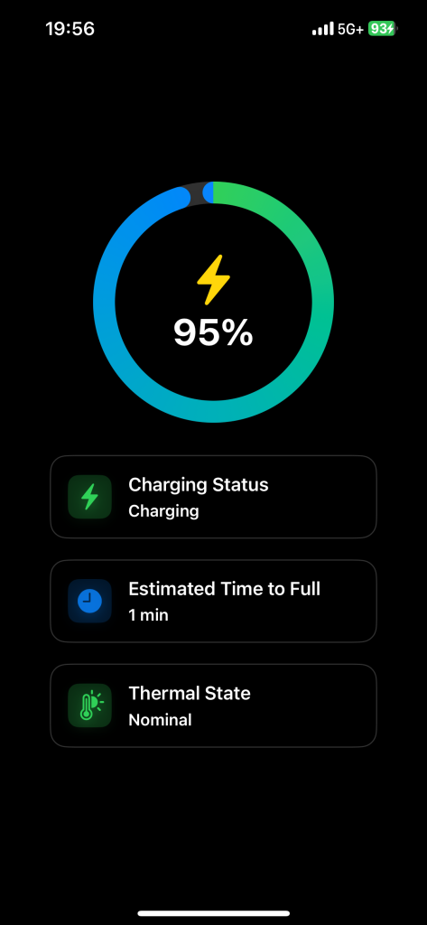
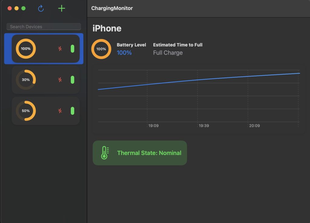
    • Completed the development of iOS and macOS apps for real-time monitoring of charging status.
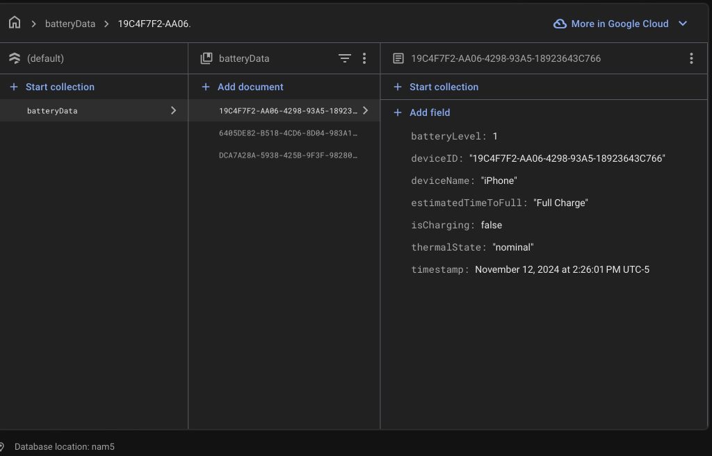
    • Integrated Google Cloud Firebase for centralized data storage, enabling users to view and manage charging statuses across multiple devices.
    • Conducted software testing to ensure real-time updates with an average delay of less than 500 milliseconds and consistent synchronization across platforms.
  2. Computer Vision System Development
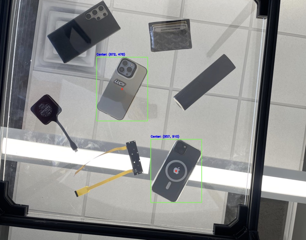
    • Finalized the object detection module, achieving 90% accuracy in phone detection.
    • Implemented a two-frame difference technique to identify significant changes and avoid unnecessary YOLO model usage, improving performance.
    • Enhanced the YOLO pipeline to detect phone locations and return their center coordinates with high precision.

System Validation

  1. Gantry System Testing
    • Conducted repeated forward and backward movements to ensure smooth, consistent motion on the X and Y axes without pauses or obstructions.
    • Confirmed that the gantry aligns with the intended design goals for X-Y movement, with full system requirements to be met after Z-axis integration.
  2. Charging Coil Testing
    • Verified that the charging coils meet design requirements for charging through acrylic boards without overheating.
    • Confirmed compatibility with different phone cases and thicknesses of acrylic, with further testing planned to gather time-to-charge data.
  3. Software Testing
    • Verified real-time status updates for multiple devices and confirmed data consistency between Firebase and app interfaces.
    • Tested object detection under various lighting conditions and orientations, achieving high accuracy and minimal false positives.

Since we have not complete our project yet, it is hard for our current implementation to validate all the user requirements and the design requirements specified in our documents. Currently, we only validate that our system can detect phone < 1 seconds, software app information update < 500 milliseconds, and vision detection system has accuracy > 90%.

We believe we are currently on track.

Next week’s plan:

  1. Gantry System
    • Assemble and test the Z-axis manipulator to enable full 3-DOF movement.
    • Combine the central manipulator with the existing gantry system for complete testing.
  2. Charging Coil and Pad
    • Redesign and 3D print the charging pad holder for the 5mm acrylic setup.
    • Conduct experiments to determine the time required to fully charge phones with the 12W charging module.
  3. System Integration
    • Begin integration of the computer vision system with the gantry system.
    • Test communication between the vision system and the gantry for seamless control of charging pad movement.
  4. Further Testing
    • Perform end-to-end testing to validate the entire workflow, including phone detection, pad movement, and real-time status updates on the apps.


Here are some pictures of our system:

Corners:

Software:

Charging:

Harry’s Status Report for 11.16

First, the manipulator for the center part (moves up and down) is drawn and printed. Shown as below:

The third motor will allow the center part to move up and down. The motor will be connected to a shaft. We will obtain the shaft when the central manipulator is printed out.

This week we focus on the gantry system by combining all the printed parts. We went to the machine shop to cut the aluminum extrusion, the rail. We use zip ties to tighten the belt. we test x-axis and y-axis and the gantry can move very smoothly on both axis.

Large amount of time was put into gantry testing. The belt vibrated a lot at the beginning but we found out the problem was caused by nails and belts that are not tight enough. Many trails were implemented and now the gantry can move without restriction quietly.

Steven and I worked on the gantry system together this week and more details will be included in his report. Notice we made the whole gantry system together so there isn’t clear work division between us. Since the gantry system is quite complicated, two people are needed to complete it.

Next week, we will begin assemble the center part for z-axis movement testing. Charging pad holder will be redesigned ant printed. Camera will be introduced to combine with the existing gantry part.

Verification

  1. Gantry System: gantry system can move freely and smoothly on x and y axis. This situation is desired. We let the gantry move forward and backward a lot of times to view the movement. We intend to ensure the gantry is move straight back and forth without pause and stuck. The part we did aligns with our goal for gantry system design. However, because our gantry system can only operate on x and y axis, the system requirements is not fully met until the central manipulator is built and tested.
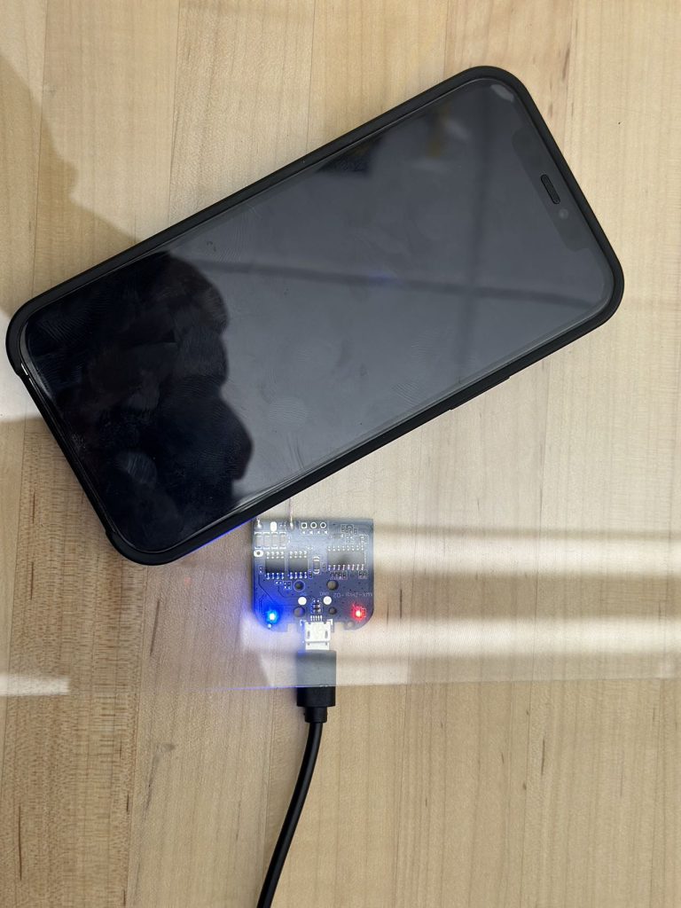
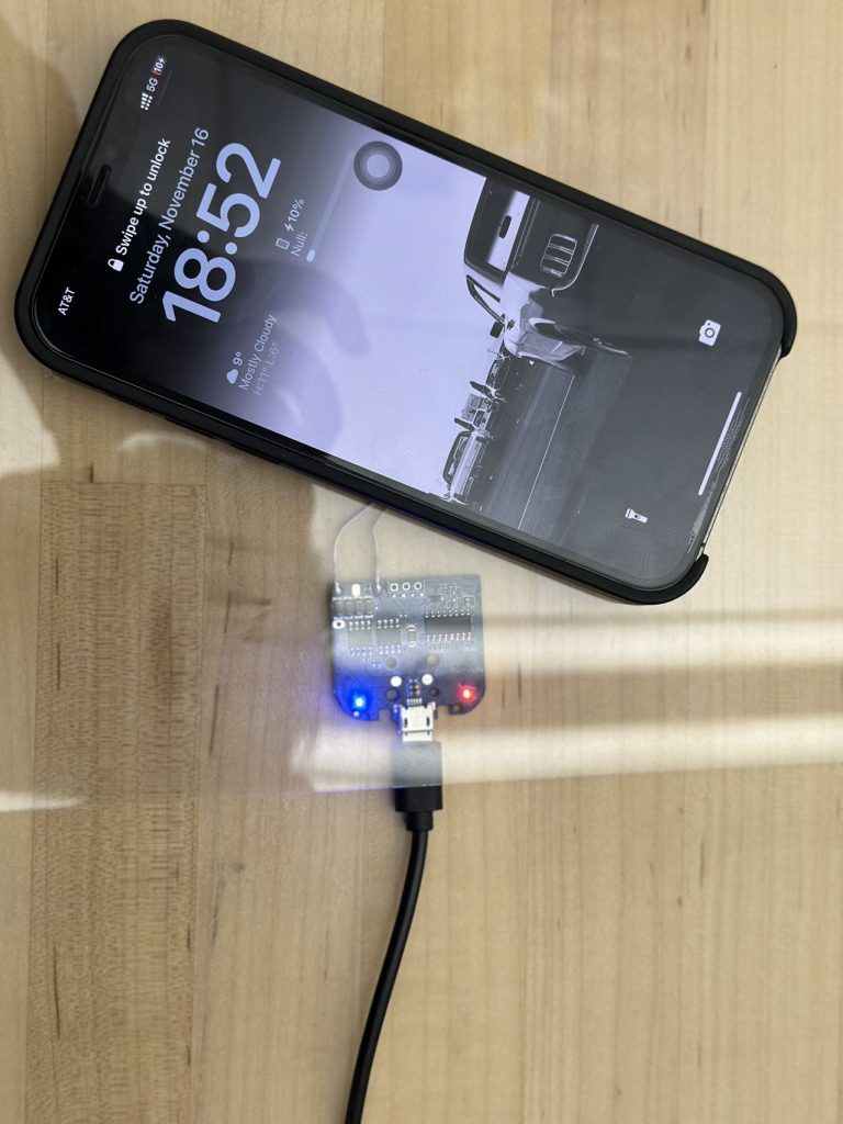
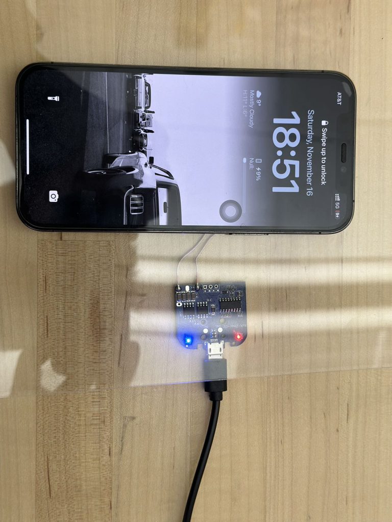
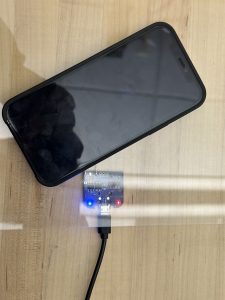
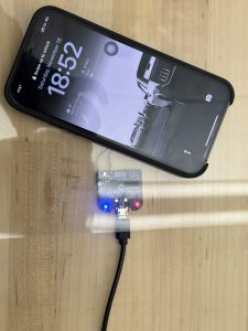
  2. Charging coil: We bought two types of charging coil and verified them  1) they can charge the phone when placed beneath the acrylic board. 2)The phone does not heat up to a very high temperature. As shown below when the blue light turns on, the phone is being charged. When the red light is on, the phone is not charged. For the 3mm acrylic board, phone can be charged with back cover or non precise alignment. For the 5,, acrylic board, phone can be charged without back cover. Relative precise alignment is needed.      5mm board:   3mm board:   This meets the design requirement of successful charging. Further data will be obtained regarding the time to fully charge the phone.

Harry’s Status Report for 11.9

This week I primarily work on the gantry system of the charging table, details are demonstrated as below.

Gantry Overview:

Front Corners (they are the same) are compose of 3 pieces:

Bottom:

Top:

Corner Tensioner:

These three pieces already submitted for 3D printing.

Rail Slider – Magnetic system Connector:

Block that fix the left and right end of the magnetic system rail:

Motor Side Corner:  (bottom layout, cap, and tensioner) the other side is symmetric to the side displayed as below:

Magnetic System will be further developed next week.

Overall progress on track.

Plan to finish most parts of the gantry system before next demo.


Harry’s Status Report for 11.02

This week I primarily work on the structures of our charging table. On Monday and Wednesday, the last few parts we ordered arrive so we could have a clear view regarding the components we purchased.  I examined the aluminum extrusions that will be used to form the frame of the table then studied on parts that could connect them. I used Fusion 360 to draw out some important parts as described below.

  1. Table upper corner: this part is used to hold the two transparent thin layers(either  acrylic or glass)   This component had already been submitted for printing at TechSpark on Thursday. We will gather the four pieces on Monday for further testing.
  2. Transparent layers side holder (further support two layers)
  3. Charging pad holder (will place the coils inside the groove and on the bottom of the charging pad holder will have magnets that allows connections with gantry system) 

3. Bottom corner


Overall, our progress is on time. Next week we will continue to perform on testing on difficult mechanical parts and consider parts that may not be good to be printed. We will then purchase them online. We will build the structure as fast as we can. Electronic parts testing will also go on.


Team Status Report 10.26

The work we completed this week can be discussed in following sections:

  1. Camera Integration and Algorithm Development:
    • We have integrated a new Stereo Camera module (NVIDIA JETSON NANO/XAVIER NX, DUAL OV2311 Monochrome Camera Module) into our system. Initial tests with the YOLO model showed a decrease in detection accuracy; hence, we are currently retraining the model to adapt to the new camera’s specifications.
    • Our work on the software app saw considerable advancement with the successful integration of the iPhone API, allowing real-time display of device information such as phone temperature and charging status.
  2. Hardware and Mechanical Design:
    • Due to a delay in receiving aluminum profiles and motor accessories, our plans to assemble the gantry system were postponed. Instead, we focused on refining the CAD models and simulating motor placements.
    • The motor support structures were fabricated using a 3D printer at the Roboclub. However, issues with the slicing process led to insufficient hardness, necessitating further printing next week.
  3. Electrical and Control Systems:
    • Wiring the Jetson Orin Nano proved challenging due to the increased number of peripherals, but we successfully assigned the motor driver to available analog pins. The setup was verified using a logic analyzer.
    • We are preparing for the arrival of the hardware this Friday, with plans to connect and debug the motor controllers and start constructing the gantry system.
  4. Documentation and Compliance: we carefully went through the comments in our design report because it seems that there are problems both quantitatively and qualitatively. For example, the use case requirements part do need to include some quantitative information. However, due to lack of detailed information, we missed some important information for several parts. Therefore, we are working on the report to refine the content. We believe we will continue to work on it next week to include more details regarding our design.

Next week, our team will focus on enhancing the YOLO model’s detection accuracy through continued retraining and testing. We’ll also conduct further tests on the updated user interface to ensure accurate data display for all phone models. Once we receive all necessary parts, we’ll begin assembling the gantry system and cutting the rails. Additionally, we’ll work on refining our design review report to address any remaining issues.


Harry’s Status Report for 10.26

This week we have obtained the camera borrowed from 18500 Inventory: Stereo Camera NVIDIA JETSON NANO/XAVIER NX, DUAL OV2311 Monochrome Camera Module. The specification of the camera can be obtained from the following website: https://www.arducam.com/product/arducam-2mp-stereo-camera-for-raspberry-pi-nvidia-jetson-nano-xavier-nx-dual-ov2311-monochrome-global-shutter-camera-module/

The Arducam 2MP Stereo Camera MIPI Module is tailored for integration with the Jetson Nano/Xavier NX platforms, enhancing our capabilities in stereo vision for applications like depth sensing, 3D mapping, and SLAM. This module incorporates two synchronized 2MP monochrome global shutter OV2311 image sensors, providing high resolution and sensitivity essential for precise depth information. It connects via the MIPI CSI-2 interface and operates with V4L2 camera drivers. Although it can achieve frame rates up to 50fps at 3200×1300 resolution, it does not support ISP processing on the Nvidia Jetson platform. We must utilize external image processing tools and applications that comply with the V4L2 framework. The camera module includes a selection of mounts and cables, but does not come with the Jetson board itself. Therefore, we are working on our openCV code for the camera, currently using Gaussian Blur for image smoothing and the Sobel Operator for edge detection. After the code done early next week we will begin testing on the camera.

Apart from the camera as well the testings for Jetson Nano, I spent a long time together with my teammates to go over the design review report. During last week’s meeting, many problems with our design report was pointed out and we need to fix all of them. For some of them we do have a clear idea while for the remaining parts we still need to consult professors and TAs. We will continue refining our design review report next week.

Overall, my progress is on schedule. For the next weeK, I plan to continue the testing on the camera we obtained last week.  At the same time, as mentioned earlier, our motors and linear rails have arrived. We will begin to divide the work and start cutting rails and construct the gantry system. For the motors, we will start testing next week as well.

Harry’s Status Report for 10.20

During the week prior to the fall break, we focused on our design review report for the project. I completed the use case/design requirements, design trade studies, and related work parts.  In the related work part, I looked into the team that has a similar project last year, discussed their problems and ways we could do better.  Some of these thoughts are reflected in the trade studies part because we modified our design several times to combine the gantry system and robot ideas.

Also, we received our central control unit: Nvidia Jetson Orin Nano. At the same time, we tested some basic circuits during the class time at Techspark. Also, we implemented some testing on the camera we have because we haven’t got the ordered camera yet. We looked into come basic implementation regarding image filtering and segmentation and we will continue to work on our original camera next week. After we got the Stereo Camera Nvidia Jetson Nano, we will compare these two devices and pick the one that is easier to program.

For me, this week I mainly familiarize myself with the Nvidia Jetson Orin Nano. There are detailed descriptions on Nvidia website regarding the ports names and usage. With my own keyboard and monitor, I’m able to connect the Jetson Nano with them using the DisplayPort connector. Then I was able to begin programming. At the same time, I gathered info about the gpio header pinout.

https://jetsonhacks.com/nvidia-jetson-orin-nano-gpio-header-pinout/

I followed this pinout to implemented some basic testings, for example use wires and breadboard to light up and LED, power a motor driver, etc. Also, this pins support UART, SPI as well as I2C communication protocols. I also test the existing camera with the Jetson Nano to complete some basic image filtering. It works now but I believe further testings should be implemented because this time I randomly take pictures. Detailed testing regarding taking pictures from the bottom to view the electronic devices on top of the table should be taken into consideration. We only confirmed there are transparent acrylic boards in Techspark but haven’t test them together with camera. I also dig into camera settings and found that environmental lights may also affect image filtering results, so we assume this table is placed indoor without too strong light from the top.

Overall, my progress is on schedule. During this week I begin to familiarize myself with Nvidia Jetson Nano and implemented some basic testings. Next week we will combine the Jetson Nano with components that will arrive. We will continue to develop the image filtering code with our existing camera. At the same time we will begin to construct the gantry system as well after receive the corresponding components.