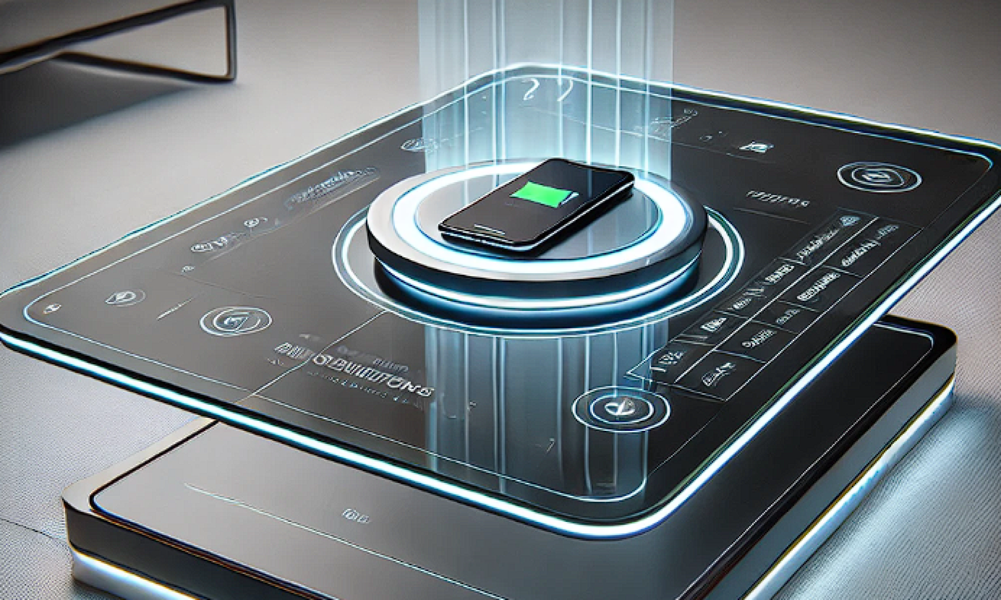
First, the manipulator for the center part (moves up and down) is drawn and printed. Shown as below:

The third motor will allow the center part to move up and down. The motor will be connected to a shaft. We will obtain the shaft when the central manipulator is printed out.
This week we focus on the gantry system by combining all the printed parts. We went to the machine shop to cut the aluminum extrusion, the rail. We use zip ties to tighten the belt. we test x-axis and y-axis and the gantry can move very smoothly on both axis.
Large amount of time was put into gantry testing. The belt vibrated a lot at the beginning but we found out the problem was caused by nails and belts that are not tight enough. Many trails were implemented and now the gantry can move without restriction quietly.
Steven and I worked on the gantry system together this week and more details will be included in his report. Notice we made the whole gantry system together so there isn’t clear work division between us. Since the gantry system is quite complicated, two people are needed to complete it.
Next week, we will begin assemble the center part for z-axis movement testing. Charging pad holder will be redesigned ant printed. Camera will be introduced to combine with the existing gantry part.
Verification
- Gantry System: gantry system can move freely and smoothly on x and y axis. This situation is desired. We let the gantry move forward and backward a lot of times to view the movement. We intend to ensure the gantry is move straight back and forth without pause and stuck. The part we did aligns with our goal for gantry system design. However, because our gantry system can only operate on x and y axis, the system requirements is not fully met until the central manipulator is built and tested.
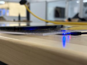
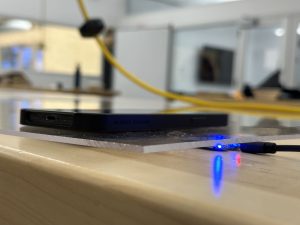
- Charging coil: We bought two types of charging coil and verified them 1) they can charge the phone when placed beneath the acrylic board. 2)The phone does not heat up to a very high temperature. As shown below when the blue light turns on, the phone is being charged. When the red light is on, the phone is not charged. For the 3mm acrylic board, phone can be charged with back cover or non precise alignment. For the 5,, acrylic board, phone can be charged without back cover. Relative precise alignment is needed. 5mm board:
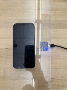
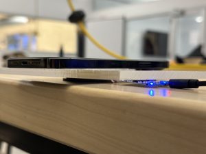 3mm board:
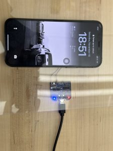
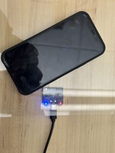
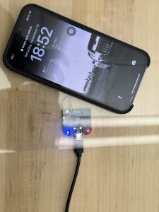 This meets the design requirement of successful charging. Further data will be obtained regarding the time to fully charge the phone.
