Kaloyan’s Status Report for 4/25

This week, I worked on adding some more features to the VGA display, finishing the debugging for polyphony, and looking into a basic LFO implementation.

For the VGA display, I’m working on creating a live oscilloscope, that will be reactive to the current note + effects the user is utilizing. However, this is adding additional complexity to the VGA pipeline: since the oscilloscope operates based on buffers of audio data being captured, it causes the VGA output to be delayed by one clock cycle. Although the trigger point detection and actual audio capture can be hidden by the wait times for VGA sync, the actual readout of BRAM cannot. I also plan on adding something to show the current drum pattern.

The polyphony debugging ended up being much simpler than expected. The clock domain crossing I had previously accounted for (with the difference in clock speeds for the round robin-arbiter and actual audio generation) introduced a bug where the keypresses were not being detected properly. By removing this, the arbiter worked properly and 4-voice polyphony worked!

Finally, I began implementing a basic LFO. Since we already have the existing code for our actual audio generation, it was quite simple to port it over to the LFO. Fundamentally, we are still working with the same phase accumulators and shapes. The only difference is that the frequency is now much lower, and user controllable. I have not finished implementing this feature yet, but if it works well I can also see it being viable to have multiple. Our entire 4-voice audio generation logic was only utilizing 18% of logic and 2% of memory, meaning that should be able to be fine in terms of utilization.

Team Status Report for 04/25

We spent the week as a team working on perfecting our individual subsystems and working on perfecting the system interface and integration. Moreover, we conducted some user testing with mechanical engineers in TechSpark, as further detailed below. Everything is very much in progress, and we are well on track to be done with our project on Wednesday and have everything set up for demo day. Our schedule did not change, and there are no significant risks to project progress now that our user interface has been completed and is easy to use.

These are the set of tests we conducted for subsystems and the overall system:

Latency:

There were two main types of latency tests conducted, which were MIDI End-to-end latency tests and overall system latency tests. As mentioned in our final presentation, the following involved using an oscilloscope and cursor measurements to get the difference in time between the first MIDI bit being sent and the last signal value being sent out to the audio CODEC (and the GPIO pin connected to the FPGA for MIDI end-to-end latency tests).

We tried out all three types of MIDI commands supported in our system (noteOn, noteOff, controlChange) and averaged the latency out through multiple attempts (10 for each command type). This would be in conjunction with different types of signals and effects applied on them. We got the following values for such.

MIDI End-to-end latency: 1.324 ms

Overall System latency: 2.384 ms

This was all within our required <5 ms latency requirement, so no aspect of the system needed to be refactored.

Audio Accuracy:

While we use “audio accuracy” as the broad term for this, we really mean how accurate notes are with regard to cents. We recorded audio for all the supported notes in the Monoprice keyboard (with all four types of signals), and used a spectrum analyzer to extract the frequency value for the specific notes. We then averaged out the difference in cents to the expected value, and got the following:

Average Frequency Difference (in cents): 0.33 cents

Highest Difference in Frequency (in cents): 1.42 cents

This was all within the difference we were trying to be under, which was 5 cents, so no aspect of the system was changed.

Audio Quality:

For audio quality, we tested our different signals for the following metrics:

Total Harmonic Distortion (THD)

Signal to Quantization Noise Ratio (SQNR)

Spurious Free Dynamic Range (SFDR)

We recorded the output for each signal on a SystemVerilog testbench, capturing such on a .txt file. Afterward, we used a Matlab script and corresponding builtin functions to extract the metrics for each signal.

It yielded the following:

Sine

THD: -55.29 dB

SQNR: +44.99 dB

SFDR: +59.32 dB

Square

THD: -6.31 dB

SQNR: +30.10 dB

SFDR: +9.54 dB

Sawtooth

THD: -1.90 dB

SQNR: +25.33 dB

SFDR: +6.02 dB

Triangle

THD: -18.33 dB

SQNR: +108.37 dB

SFDR: +19.08 dB

These results are mostly expected, as sawtooth waves have strong harmonics and square have odd harmonics. The other numbers, particularly for sine waves, are not necessarily ideal.  While triangle waves indicate barely any quantization, the rest show some semblance of such. At the moment these were measured, we were using 1024 samples for our waves. We had assumed that these were of high enough resolution to avoid signal quality issues, but going with a higher sample number could possibly mitigate some of these issues. While our sound was “good enough” at that point, we decided to attempt increasing our resolution to 4096 samples on Sunday, with the results to be recalculated for our final report.

ADSR:

For ensuring ADSR was working properly, we implemented a SystemVerilog testbench to capture and compare different ADSR values and their subsequent effect on the output. Afterwards, we compared this output and inspected the result to determine whether the envelope shape matched what we expected. This, combined with on-device testing, helped show that ADSR was implemented correctly.

Polyphony:

To ensure polyphony was working properly, we designed a SystemVerilog testbench. Because we were effectively creating a round-robin arbiter, understanding the logic of the module was not too difficult. However, on the actual FPGA there were still issues with how the input was being processed. To determine the source of these bugs, we implemented live debugging tools (specifically using the seven segment display and Arduino LEDs).

VGA:

For testing VGA, we knew that once we had some kind of image on screen it would be easy to continue development (and would most likely require no further testing). Thus, we deemed it most time-efficient to examine different VGA implementations online and go straight to synthesis rather than simulation. This is because we believed that the setup time for a debugging setup outweighed the time it would take to just set it up on the actual monitor. There was a slight bug with outputting the VGA SYNC clock, but this was an issue that came after synthesis anyway.

Effects:

To evaluate system behavior, we first implemented a SystemVerilog testbench to test specific components by inserting them into the wavetable/phase accumulator path and observing the resulting output. In parallel, we developed a fixed-point model in Python and compared it against a floating-point reference to quantify the error introduced by quantization. If this error fell within acceptable bounds, we then validated the fixed-point Python model against the SystemVerilog testbench results. To provide an example, during testing, both in simulation and on hardware, we observed that FM modulation introduced significant sideband activity, which ultimately led us to exclude it from the design.

UI:

For the user interface, we focused on minimizing setup time, targeting under five minutes for a first time user. To evaluate this, we recruited volunteers individually from TechSpark, provided them with a basic set of instructions, and timed how long it took them to complete the setup on their our computers. The results were encouraging: all participants finished in under five minutes, with the longest time recorded at approximately four minutes and thirty seconds, indicating that the system met our usability goal.

On average, we found that
Setup Time: 3 minutes and 16 seconds

We tested the measurements of the chassis (to make sure that it’s portable enough) with a tape measurer, and found
Chassis Measurement: 22.1 x 11.2 x 5.5 inches

Moreover, we weighed the overall system itself quite recently (chassis, FPGA, breakout board, Arduino) with a scale, and found

Chassis Weight: 6.72 lbs

Which was a little over our expected weight (5 lbs), but no changes were made to the system as it was within a reasonable bound due to the fact that we had not accounted for all of the interface additions (keys, LCD, plaque) in our initial weight metric. When we asked users, they said the system was portable enough to carry around, which also influenced our decision to make no changes to the chassis.

MIDI Interface:

To test the MIDI interface for correctness, I set up the FPGA’s hex display to show both the key note values and velocity values being transmitted to it. Moreover, the knobs were tested through the same manner, with the knob value and channel being displayed in the same location as the note values/velocity. I thoroughly tested for each of these, which verified that both the MIDIFsm and UART modules functioned properly. Apart from this physical testing, I had previously set up a SystemVerilog testbench to assert correctness with my UART modules, since adhering to timing rules was one of the most pivotal components of such. 

Audio Interface/Communication Protocols:

Interfacing with the FPGA’s built in audio CODEC required the utilization of two communication protocols: I2S and I2C. For those two, I’d developed SystemVerilog testbenches to test correctness and accuracy with regard to timing, since it’d be hardest to debug in the physical board with an extremely fast clock.  Things like checking for correct timing on the acknowledge bits and start/stop conditions were all covered. After this, testing if the audio interface worked went hand in hand with testing the different types of signals. I would connect audio output onto an oscilloscope and play different signals, checking if it visually matched whichever had been chosen. Apart from that, we’d check if the audio of the waves would correspond with what we had expected to hear.

Jose’s Status Report for 04/25

I spent the first part of the week conducting basic user testing with Mihail and generally receiving feedback on the design of our chassis. We checked how much it took (on average) to load all of the code onto the FPGA itself, and had some users try to set it up based on a simple instruction sheet we had set up. While the numerical results looked good (and are discussed in depth in the team status report), it was clear that the UI itself was not fully integrated. As previously mentioned, I received good feedback from testers on things that would add onto the user interface, with one of them being buttons for the drum-track. Most of the people mentioned that something akin to keyboard switches would be good, so I ordered such switches in combination with spark fun cherry MX breakout boards:
Cherry MX Switch Breakout

Once I received all of the components, I soldered one of them with a switch and set it up on a breadboard to check that it worked before modifying the box. This included creating Arduino code that would account for debouncing, which was something I had not initially considered for keyboard buttons. It all worked without many issues (since I feel that my soldering skills have improved after dealing with the SparkFun MIDI breakout board), so I moved on to placing everything on the chassis.

This second portion of work for the week began with three reveals: 1. I had measured the knobs incorrectly such that they do not fit on the circular hole in the chassis, 2. I did not account for buttons or LCDs in my original design, 3. I did not consider that adding new components would require laser cutting the components from the beginning (as everything glued together would not be compatible with the machine at TechSpark). Because of that, I spent a significant amount of time redesigning the chassis, taking measurements for the knobs, keys, and LCD to make everything fit properly.

This, furthermore, required soldering all of the other cherry MX breakout boards and pins, which took up a significant amount of time (particularly since I messed up the initial orientation to solder in which required desoldering).  Once the box was laser cut again, I put all of the components together, which resulted in the following interface being finally set up:

Now that everything is hooked up properly, testing and general setup should be much quicker in the final days of implementation. Everything on my end is going well, and there should not be much left for me apart from conducting more user testing/correctness testing for our report and setting our project up for demo day.

Mihail’s Status Report for 04/25

This week I gave the final design presentation for my team, continued debugging efforts for the filter before pivoting to a new approach, integrated the LCD display into our system, and continued testing.

The start of my week was spent preparing the slides for the final presentation, and then I spent substantial effort Sunday, Monday, and Tuesday practicing it.

I spent more time trying to debug the filters in parallel to this but was unable to find the underlying bug. I’ve decided I’ll have another teammate look at the issue, but instead of allowing this to block progress, I decided to work around the problem and implement a “pseudo-filter”. The module looks at the primary frequency being played and uses that to attenuate the inbound data, and takes in cutoff frequencies and gradients as inputs. I’ve designed it so that it can operate as a  low, high, or bandpass filter depending on user inputs, with independent cutoffs and gradients on each end. Users will be able to program the filter type via the UI.

With the workaround implemented, I wanted to focus on system integration. I selected a LCD display to be added to the system and programmed it. This was slightly difficult since the graphics system was different from what I was used to (X and Y coordinates were flipped and pixel coordinates did not start in the top-left corner as is standard). I managed to implement functions that allow me to display arbitrary strings on the display, and added code to our Arduino to initialize and display messages on the LCD code as well as interface between the MIDI and FPGA. After adding debouncing logic to avoid rewriting values every single time a knob was turned (instead, only after a set amount of time had passed), I had the LCD display input parameters. As of now, this is ADSR inputs. Once the system is fully integrated, I will have it display the different values for whatever the filter selection input is currently on.  We’ll still have the VGA output provide visual cues for what certain effects are doing, while the LCD display is designed to give numerical data.

Finally, I spent some time testing, specifically working on testing setup times, something that is still possible despite the UI not being fully integrated. I’m also preparing for another round of SQNR tests to ensure that the sawtooth and square waves are now at acceptable values.

Next week, I will finish integrating the system, perform more tests as necessary, make one last pass at the original filter implementation, and give our design expo as well as write the final design report.

Team Status Report for 04/18

This week, the team spent most of our time adding onto our implementations with new interfacing components. While the signal processing components of the system stayed the same, the overall system now accounts for VGA output and a physical box with all the general inputs that the user could need for our system. This not only makes setup much easier, but also the user experience in general is much friendlier. Moreover, we all worked on setting up testing for our system in conjunction to creating and finalizing the final presentation. With that in mind, our biggest risk is simply not being able to integrate the entire system together, as all the individual components are on track to working properly. While it’s not in our plans, there is the possibility that one thing doesn’t mesh well with the other, which would involve us putting in extra time to getting everything together working (or segmenting pieces of the system). Overall, though, we’re on track to get everything working by demo day, and our schedule remains unchanged.

Kaloyan’s Status Report for 4/18

This week, I spent time on developing the VGA display, choosing the buttons for the drum sequencer, and integrating 4-voice polyphony.

For the VGA, I was able to get an initial image running quite quickly. I followed some online blog posts and after a bug with forgetting to output a VGA clock, I managed to display a single line. I then worked on creating two modules, a static line module and a dynamic line module. I’m currently using a DSP approach (calculating the cross product between a pixel and an established line), but may switch to Bresenham’s algorithm which instead uses BRAM and precomputes all the plotted pixels without using DSPs. The static line is defined at compile time, meaning that the resource usage can be folded and done without using DSPs. Using this, I linked the values from the ADSR and created a small depiction of what the amplitude envelope looks like. The youtube video shows an example of it being adjusted using the knobs. Next, I’m going to work on displaying the drum sequencer and effects.

For the buttons, I researched different varieties. I wanted a good aesthetic for them, but also functional use. I ended up deciding to use buttons with LEDs on top to depict step pattern, an LED driver (to reduce engineering effort and controlling dimness), a perfboard, and some other materials. Once they come in, I’ll work on wiring them up and then connecting them to the VGA display.

For the remainder of my time, I worked on trying to get polyphony working. Unfortunately, I’m still debugging some weird sync issue. The clock crossing from the input domain (100 MHz) of the arbiter, which assigns key presses, to the actual audio domain (50MHz) may be causing some issue. Although multiple notes will play, their note value seems to change sporadically. I’ll keep debugging and will hopefully find the issue soon.

Throughout my time, I’ve had to learn various effective hardware algorithms/methods to efficiently implement my tasks. For example, the ADSR required careful analysis on whether to use DSP blocks or not. Since it works based on a sample tick enable, the latency to calculate the phase steps for attack, sustain, decay, and release can be hidden. This makes using the DSPs viable, since storing all the necessary LUTs in BRAM would consume too much memory. Another hardware algorithm involved the dynamic line drawing for VGA. As previously mentioned, it may be better to use Bresenham’s algorithm. For learning these methods, I have been using blog posts. I find that they go into tremendous, specific detail. Much of the time, its better than youtube videos because they cover much more ground. I find that the detailed content makes it easier to conceptualize and fully understand.

Mihail’s Status Report for 04/18

I spent the week working preparing for the final design presentation, which I will be giving, and trying to debug the low pass and high pass filters now that I could do so on board.

For the first task, I spent time working preparing the slide deck and practicing it, as well as gathering testing data with my partner, Jose. We determined it would be wisest to use different testing metrics than the ones we had originally intended, choosing to focus on latency, audio quality, and audio accuracy due to their ease of testing and higher relevance relative to our original metrics. From there, the components for MIDI processing were setup as a separate circuit and tested with an oscilloscope, while the on board components were tested by inserting cycle counts into the FPGA to determine the amount of time between an input signal being registered and a change in the output audio.

Debugging the filters has proven to be a large time sync, since I am still not achieving the results I had desired for (with the filters tending to either not filter at all, or filter too aggressively for coefficients that should still pass through a variety of the notes on board). As a result, I spent some time creating a python script that would simulate the fixed point arithmetic of the filters and compare that a golden model using floating point. Below included is the expected attenuation for the low pass filter I’ve chosen as the best candidate for final inclusion, a 5 stage, cascaded, first order filter. At this point, I am fairly convinced that the issue is with how I am dealing with sign logic, or due to some unexpected way in which the compiler is translating my RTL. I hope to have resolved the issue by the end of next week, but will be spending a large amount of time on system integration.

During this course, I’ve found that I’ve gained a lot of knowledge in how to simulate digital logic, learning both MATLAB (for the second time) and python’s numpy / scipy libraries in order to develop, test, and debug components. Additionally, I learned a lot on how to use Quartus, since my experience had primarily been in guided tutorials before, and I now feel that I have a much better understanding of the tool. For these, I’ve found that there tend to be a variety of resources online that I can use a start base for my knowledge, and found generative AI very useful to help me plug gaps in my knowledge (i.e. asking for clarifications regarding a paragraph in a article I read). From there, moving on to more technical articles such as the official documentation for a library or software allowed me to gain the knowledge I needed.

Jose’s Status Report for 04/18

Most of my work during the week of carnival involved setting up knob input from the MIDI keyboard. This required debugging and adding onto the UART and MIDI receive FSMs to account for more than one byte of data being processed (since knob inputs require both channel data and value data). Doing this required utilizing the FPGA’s hex output to display what values were being received, which allowed me to notice the bugs with the system (which were mainly timing/fsm structure related). Since most of it was building on top of already existing components, though, the work was not as painful as setting up note on/off command receiving. The rest of the time was modularizing the code so that Mihail and Kaloyan could easily assign values to the knobs without having to interface with any components they may not necessarily understand.

I spent the week after carnival primarily working on the external interface of the system, with the rest of the time being focused on getting testing data for the final presentation and the creation of such.

Most of my time when creating the interface was getting accustomed to the laser cutting interface in TechSpark. Everything was smoother than expected, though, thanks to the help of both the people working there and their video resources. I used a hinged box model extracted from the website Makercase.com, as pictured below:

I downloaded its corresponding SVG file, and modified it as necessary in CorelDraw. 

Once that was done, I used the laser cutting machine on three slabs of plywood (which was around $9 dollars, much cheaper than the 3d printing costs). It resulted in the following box (which I engraved with some designs, on top of that):

After that, I spent my time configuring the knobs that would be present in the box (the Modulino knobs that we’d ordered beforehand). I configured the code in the Arduino itself so that it could be considered the same as the knobs in the MIDI keyboard, and the data would be transferred through the same GPIO port that that keyboard data gets sent through. Thanks to the Modulino library (and the knobs’ support for QWIIC connections), setting up the I2C communication was relatively painless.

Finally, I set up the testing interface for extracting latency (both overall system and MIDI end-to-end). This required the use of the Agilent oscilloscopes present in some of the ECE labs. I set it up so that one channel would be connected to the keyboard’s MIDI output, while the other end would be connected to the FPGA’s GPIO port. Then, in the oscilloscope, I set a trigger for the falling edge of the MIDI output (when UART began sending the message). Once that was triggered, I could then use the measure feature (coupled with cursors) to measure the time difference between the keyboard sending a message and the FPGA receiving it.

Overall, though, everything is on track as it should be. Most of the work for this week was building up on previous work or doing physical work (with laser cutting), so no real hiccups were expected. My plan for next week is to add more components to the physical box setup (keys, LCDs, etc.). Moreover, conducting user testing of some sort is in our plans.

While I felt that my pre existing knowledge on digital design and FPGAs was sufficient for many of the tasks I worked on, there were quite a few that involved learning new things. Laser cutting is the first one that came to mind, as I had to learn how to use the machines in TechSpark and also the drawing software for the schematics (CorelDraw). I used a mixture of YouTube tutorials on those pieces of software (generally titled “How to laser cut a hinge box”) and help from TechSpark staff. Apart from that, learning about and implementing the I2S protocol involved reading quite a few things. In particular, I adopted my usual strategy of reading forum posts on the matter, as they tended to clearly outline the requirements for the communication protocol in a clear manner. This was the same for both UART and I2C as well. In the same vein, I used forum posts and online videos on the MIDI protocol as a basis for my FSM implementation and general debugging of the keyboard interface through the SparkFun breakout board. Finally, the tools I used for debugging (oscilloscope, matlab, systemverilog test benches) all required looking at thorough documentation, forums, and YouTube tutorials for proper use, as I had not resorted to using these in a long time. Overall, I tended to stick to informal methods of learning for these new pieces of information (tutorials, forum posts, etc.) as they tend to be the most easily digestible for me.

Team Status Report for 04/04

So far, everything is going according to plan and no major risks are present with regard to our project’s progress. As Jose’s interfacing baseline is setup, the major risk of having no button/key/tactile feedback with our system has been resolved (the video showing this is shown in Jose’s report for the week). As talked about in the interim report, the schedule has been updated to represent the work we’ll be doing on the actual overall physical interface. Since we want to make a box storing all the components and the like, time will need to be invested in designing and printing/laser cutting. Here is the updated schedule for such:

Our plan for testing the whole system initially involves playing different audio wave types/drums in combination with filters, checking that the audio corresponds to the intended filters/waves chosen. Note frequencies will be tested by using a spectrum analyzer app, making sure that the MIDI key played is accurate to the one outputted. End-to-end latency (where we’re targeting < 10ms) will be tested through an Audacity two channel recording. The first channel will be connected through the MIDI keyboard (where we can have it connected to a USB apart from the MIDI DIN) while the second is connected to  the output port of the FPGA. Signal quality/aliasing will be tested, as previously discussed, through Matlab. We’re going to record the output coming out from the FPGA through the 3.5mm cable and then import it into Matlab to compare with an ideal signal.

Jose’s Status Report for 04/04

I spent the week further working on getting the MIDI board to work with the FPGA. After arduous testing and debugging with no results (and conversation with faculty), I decided to pivot to interfacing through Arduino. Instead of having MIDI -> Board -> FPGA, I’d be doing MIDI -> Arduino -> Board -> FPGA. Because the board itself was made as an Arduino shield, interfacing is much more simplified (and also good for confirming if the issue is with the board or the RTL code). I worked on setting up the interfacing using the FortySevenEffects MIDI library for Arduino, where the Arduino would receive MIDI data through UART at a 31,250 baud rate in the board’s RX/TX ports.

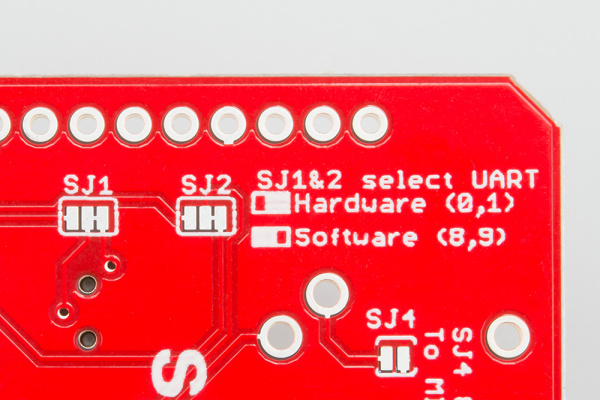
The board has two separate configurations for data transfer, which are software and hardware.
Serial Selection Jumpers

By using the software port, data gets transferred through the Arduino’s 8/9 digital pins and SoftwareSerial library, leaving the 0/1 pins for serial debugging.  This required soldering the tiny rectangles pictured above, but doing so was difficult and brought about a multitude of debugging challenges. While it ended up working for a little bit of time, the board’s decoupler IC got damaged. I ended up pivoting to the backup board, and resoldered it for the standard hardware UART configuration. While I cannot do serial debugging, I can still send out the received Arduino data through the 8/9 SoftwareSerial pins to the FPGA.

Once this was set up (and confirmed that data was being received through the Arduino’s LEDs), I connected the software TX/RX to the FPGA’s GPIO pins and integrated it with my existing UART code. Moreover, I set up the hex displays to show the note values of whichever note I’m pressing. I configured it with sound output, and was left with a functional interface for key presses. Here are the two videos showing the following results.

Key Pressing:

https://youtube.com/shorts/B49BmfY5yy4?feature=share

Hex Display Setup:

https://youtube.com/shorts/aDOGcXA_wZU?feature=share

My plan for next week is to configure the knob interfacing with the keyboard and begin drafting/setting up the physical interface for the entire product (utilizing CAD for laser cutting or 3d printing depending on whichever approach we choose). Everything is on track now that the interfacing works for keys, as the further work builds off of this.

My plan with regard to testing this system (and further interface additions) involves utilizing the hex displays that I’d previously set up. As shown already, I’m using it to make sure that the note number and velocity values when pressed are correct, but my plan will be to use it for the knobs and sliders as well. Key latency will be tested utilizing an oscilloscope, measuring when the FPGA’s GPIO pin receives MIDI data relative to when it was pressed. Audio validation, for now, has been purely auditory and will further be tested when we begin sampling the signals for audio quality data. While accuracy needs to be tested through these means, overall correctness is tested through the previously mentioned technique. Apart from auditory tests, though, the planned tests have not been conducted.