
April 19-25
The start of the week focused on final presentations. Matthew was able to finalize the shoe/foot model while Joon was able to finish the app. We decided to do as much testing as possible, which included testing computer vision models, pickup, and nav. Even though nav wasn’t completely finished and still needed tuning, we were able to run some simple tests (it failed for all trials when there were 2 obstacles).
After final presentations, we decided we would split all of work for the last phase of our project. Because we still had a final report, final video, final poster, and final demo, Jasmine would focus more on navigation while Matthew would take care of the final poster and report. Joon would take care of the final video and additional testing for his app. Once Matthew finishes the final poster/report, he will be able to transition to help Jasmine with more testing and debugging for nav.
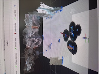
Nav: We have finished our navigation, using a script utilizing Laser Scans (see image below to see what they look like). It navigates forward until it can’t because there is an object, then it turns. This navigation script works very well, and is much simpler and relies on a lot less than Nav2. Nav2 was working, but is inconsistent, and created some ghost walls, so we decided to pivot.

We have our whole pipeline working using an FSM for states to make sure everything happens in order. The only thing left is to update our website with new code, and to test and refine. See below for a video:
Here is a video of our whole pipeline working: Retriever Rover
April 11-18
The main focus of this week was navigation. Matthew worked on the shoe/ankle YOLO model and updated the scripts for making movement less jolty, and the pickups more accurate.
At the same time, Jasmine and Joon worked on the Navigation. Joon wrote a Creeping Line navigation algorithm. However, after talking with the professor, it was decided that it isn’t robust enough. At the same time Jasmine worked on getting Nav2 to work. Jasmine and Joon both worked on making the Nav2 script to use frontier search until it detects an object, then use the script that was tuned previously to do pickups. It has been tested on a small table, but not a big room yet. Navigation was the main goal of this week.

The biggest components that could jeopardize our work is if our navigation isn’t great which we plan to test tomorrow. Also, our motor drivers are shorting unexpectedly, which we’ve already had to replace 5 of them. This happens for a number of reasons, but we just have to make sure our physical components are in place and not moving around.
We are still on schedule. Next week we should incorporate the webapp which is already written, and the YOLO shoe/ankle model. And we will test it a lot.
April 5 – April 11
This week, we first improved the algorithm that we demoed for the interim demo. Instead of doing a one shot algorithm, we now drive up to the object in two stages and recenter our robot twice in the process. This allows for a lot more give in how off center or rough the terrain is (sometimes, rough terrain causes our robots trajectory to curve off).
On the mechanical side, we incorporated a better electrical mount and walls to redistribute weight throughout our robot.


Our robot is able to move more smoothly and jolt less.
Here is our meeting presentation: Retriever Rover 4_13_26
March 29-April 4
This week, we did our interim demos and fixed a lot of parts that broke. In testing, our arm fell off, the gripper broke, and our motor driver broke. We had temporary fixes for all these problems for our interim demos, but replaced all the parts after.
Here are our interim demo slides: Retriever Rover Interim Demo
Here is our meeting presentation: Retriever Rover 4_6_26
On the mechanical side, our batteries finally came! We incorporated them into our rover so now all our components are powered by the battery instead of the wall. We still have to do some cable management, and are thinking of CADing something for the front of the rover for holding an Arduino and load balancing. A risk we have right now, is that our rover is very back heavy. When we run it, it falls backwards. We will have to move components around or add weights to the front to be able to load balance our rover.
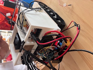
On the firmware side, we tuned our rover to consistently pickup an object. Having consistent movement helps for tuning. We also updated our navigation script, but haven’t tested yet. Next week will be dedicated to getting navigation working.
March 22-28
This week, we made a lot of progress in preparation of the interim demo.
First, we were able to integrate a preliminary (small) ML model with our robot arm for pick ups of different orientations for our box.


This was a pretty big deal for us, as it was our minimum goal for the interim demo. That being said, we put the rest of our efforts on integrating the drivetrain with the rest of our system as well.
After wiring up the motor drivers (THEY FINALLY ARRIVED), we were able to get the drivetrain wheels moving. The one issue was that we had a huge amount of components hanging off the back of our drivetrain (meaning that movement would be nearly impossible without unplugging something).
Thus, we decided to CAD a component holder for our motor drivers, Jetson, and arduino. At first, this holder was very large and hung off the back of our robot by a lot.


Thus, we decided to pivot and switch to a more vertically stacked holder. Instead of holding the motor drivers, we would instead hold the battery and store the motor drivers inside the drivetrain frame (which would also be easier for wiring because they would be closer to the motors).


After 3D printing all of these components (and rewiring everything), our robot is now able to move on the ground! (with the exception of the battery).


On the ML side, we were able to implement a significantly larger model later in the week.


This model was able to detect orientations (instead of calculating them directly using math) with a much higher accuracy.
March 15-March 21
The motor drivers arrived on Friday, so we weren’t able to do anything with the drivetrain yet. However, we plan to work on this part extensively on Sunday. This week, we made a lot of progress with the overall mechanics of our robot. To start, we were able to CAD a dual purpose arm and camera mount. 
The hexagonal platform at the top is used for mounting the arm, while the singular hole on the front is used for mounting the camera. After 3D printing, this is how the mount looks on our robot:

With this mount, we are able to raise the reaching height of our robot by around 3 inches as well as fix an angle for our camera.
On the machine learning side, we decided to retrain our first iteration on a custom dataset instead of a publicly available one. This first iteration served as a small test and only used a small set of 40 images.

While this is able to make detections, we were using math to calculate the overall angle. Essentially, we were calculating the angle of the corner (that doesn’t have blue within the bounding box). This approach sometimes worked, but had a lot of inaccurate predictions due to the fact that different orientations had different angles. We are currently implementing a second iteration with around 600 images that predicts the box as well as the orientation (not angle). After getting the orientation, we then plan to use math to calculate the angle again. If this approach doesn’t work or is inaccurate, we can easily just relabel our dataset to also include angle (but using categorical bins like 0-45, 45-90, etc.) as we have already done half of the work. We believe that we can get this part of the project done by Tuesday.
On the Jetson side, we have gotten our RealSense D455 camera subscribing to ROS camera topics. We are using the /camera/camera/color/image_raw, /camera/camera/depth/image_rect_raw, and /camera/camera/depth/camera_info topics for perception. The image_raw is the rgb images, the image_rect_raw is the depth, and the camera_info is used to get camera intrinsics. We have our perception node working. It subscribes to these topics, does YOLO inference on a preliminary model that we trained, and does some calculations to get object orientation, and an x,y,z position in meters from the camera. We also created a custom ROS topic to publish to that contains the x,y,z position, the object orientation, and the object type. Right now, we are using a 30% confidence threshold for testing, but after getting our updated model we will use a 95% confidence threshold. Also, as mentioned above, we are calculating the object orientation, but after getting our updated model we will just use that for orientation.
The navigation stack is written, but untested. We are subscribing to the custom topic from the perception node, and changing our global planner based on that. We are using Nav2 to do local planning and global planning with our predetermined coordinates. After testing our navigation, we will update our waypoints, and our algorithm as needed. We also have to hook up our motor drivers and get them working with the Arduino. We also have to get our Jetson sending this motor control topic information from ROS to the Arduino so everything can work together.
Here is our github link: Github
Here is our meeting presentation: Retriever Rover 3_23_26
March 7-14
Unfortunately, the motor drivers did not arrive this week, so we were not able to get the drivetrain to start moving. That being said, we were still able to make progress on our robot. One potential issue that came up while writing our design report was the height our robot was able to reach. While we had a goal height of 83 cm, our Braccio arm could only reach 50 cm (without a base), we realized we needed to extend the arm quiet a bit. Thus, we added a secondary linkage (from our extra Braccio arm). While added around 10 centimeters, (our drivetrain is around 10 centimeters tall as well), we will still need to add an additional 10 centimeters. We plan to do this by adding a buffer plate in between the arm and drivetrain. We feel that this buffer plate would be strategic not only for helping us achieve the height we need, but also to give us more space to mount our camera, Arduino, and Jetson.
While reprogramming our Arduino, we realized some potential issues with the torques on our servos generated by gravity. For the servo where we added an extra linkage, it would really struggle to move from one extreme angle to another while opposing gravity. Thus, we added some additional positions into our Arduino code to ensure a more smooth angle transition. Instead of going from one extreme angle to the other, we added in intermediate phases (initiated by other servos) to minimize the amount of torque on our arm.


To give a better explanation, instead of directly going from the left phase to the right phase (pick up to deliver to human), we instead take the following route:


As you can see, we take a more backwards lean in phases B and C with our bottom most joint so that our middle joint can have an easier time going vertical.
On the software side, we have ROS2, Nav2, and OpenCV installed. We also have headless connection working. We will next connect the camera, make sure it is publishing ROS topics, then work on the Nav2 stack. We have a better idea of how our navigation is going to work after meeting with our professor and TA. We are going to have coordinates (in meters) as waypoints that we hardcode of the room. They should work for any room we are given. It is specified more in our design report, but we are going to add on to that algorithm. We want to include more waypoints rather than just having 4. Potentially in a criss-cross pattern so that it is more robust and searches more areas. For example in HH 1307, there are 2 columns of tables. If we had a criss-cross pattern of waypoints, the robot would be able to search in between those tables and locate an object. Our goal is more accuracy rather than speed. We may edit our algorithm as we test, though.
We are also training a YOLOv8 model and it is working decently. We trained it on a dataset of boxes from Open Images Dataset v7 for now. It is also able to detect the length from the camera to the object well. We will have to test if it works on our boxes, and potentially train it on our boxes as well.
Feb 22-Feb 28
This week, the team disassembled our Braccio arm to debug our servos. It turns out that the servo horns (plastic) were worn about by the servo gear (metal). Luckily, that also meant that we did not have to replace the servo motors themselves, we only had take care of the servo horns. After reassembling our robot with new servo horns, we decided to implement a program to get the robot arm to pick something up. We also tried to control our drivetrain using an H-bridge, but we did not have the right parts. We ordered some motor drivers and should have it right after spring break. We plan to make this task our top priority for next week. Finally, we completed our design review. Going through each of the sections helped us solidify the design in our heads for the next half of the semester.
While doing the design report, we realized that we did not need an ESP32. Instead, we could simply rely on the Arduino Uno and use the Jetson for WiFi communication. In addition, because our Braccio arm is able to pick up a box, we have decided to not purchase a different robot arm, but instead a second Braccio arm (so we do not have to reprogram our robot halfway into building it).
Part A-Jasmine) For global factors, the design emphasizes accessibility, affordability, and ease of deployment across a variety of environments. The interface is designed to be simple and intuitive so that individuals without technical expertise can interact with the system. Because the robot can be controlled through a web-based interface, it is accessible to anyone with internet access and a connected device. The system is also designed to be affordable by using modular hardware components that are widely available and easy to replace. It is also designed for a number of indoor environments of all shapes and sizes. By using autonomous navigation and mapping software, the robot can adapt to different layouts without requiring extensive customization. This makes the solution applicable not only in academic environments but also in homes, workplaces, and any indoor rooms without stairs.
Part B-Matthew) Our robot is going to be serving older people. However, in a lot of cultures, AI and new technologies are not as accepted as they are in the U.S. Some cultures may not be able to fully trust a robot, especially one running using an artificial intelligence model. Although this is not part of our MVP, we may consider making our robot more culturally acceptable by these communities if we have time. For example, we can program some gestures of our robot to emphasize the fact that it is merely there to serve. These features may include using very graceful and slow movements and not sharp and sudden ones. Moreover, a lot of the time, people are skeptical of robots that seem to resemble humans. The fact that our robot is on wheels and doesn’t have any humanoid features (except for maybe the gripper) can prevent people from fearing our product. Finally, something else that can be considered is the fact that cell phones are now becoming more and more acceptable throughout cultures. Because our device is linked with a cell phone (through an app), cultures that have accepted cell phones may be more willing to accept our retriever.
Part C-Joon) From an environmental perspective, we considered how the design and hardware choices of our robot may affect natural resources and electronic waste. Our system relies primarily on commercially available components such as the Arduino Braccio arm, Jetson Orin Nano, and depth camera, which allows us to reuse existing hardware platforms rather than designing entirely custom electronics. Using modular, off-the-shelf components also means that individual parts can be repaired or replaced without discarding the entire system, which helps reduce unnecessary electronic waste. Additionally, the robot is designed for indoor operation and does not require significant energy consumption beyond its embedded computing platform and motors.
Feb 15- Feb 21
This week, we were able to assemble our robot and test the servos of our arm. We learned that 3 out of the 6 servos are dead and will need to be replaced. Currently, this is the biggest risk that can hinder our project. Although we already have replacement servos (from roboclub), we will need to make sure they actually work and are compatible with the Arduino braccio shield. Once we finish replacing our servos, we will also have to test and see if they are strong enough to actually grip and lift a box. If we run into too many obstacles with this plan, we can fall back on the other arm we are purchasing (which will arrive after spring break).
A couple of design changes will have to be made. The arduino braccio robotic arm we got from inventory uses an arduino uno with the braccio shield to interface with the arm. We originally wanted to use an ESP32 as a microcontroller to connect with the motors for the drivetrain, the robotic arm, and the webapp. However, we now have an extra arduino uno to interface with. We will first test the arduino braccio arm to see if it is strong enough, in which case we will use the uno for arm control and the esp32 for motor control and webapp interfacing. However, if we don’t use the braccio arm then we just will use the ESP32.
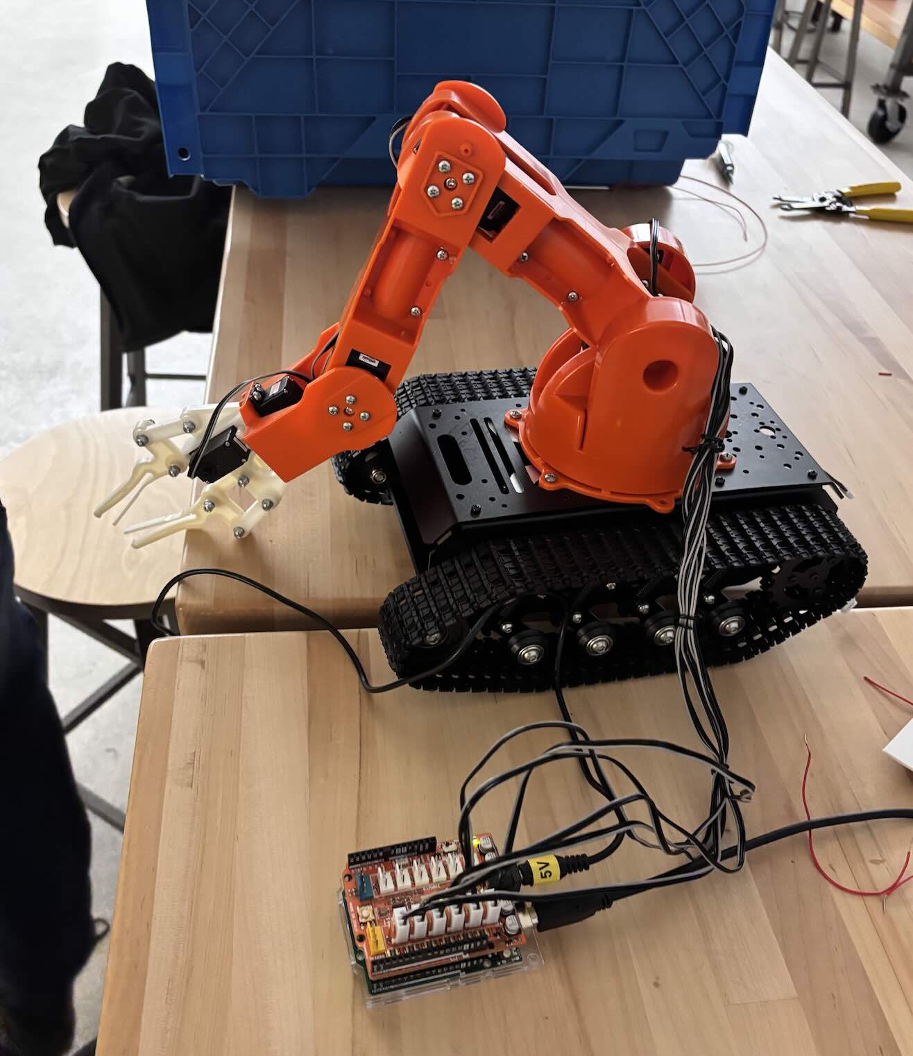
Here is an updated picture of our assembled robot (we still will eventually have to put the camera, batteries, and microcontrollers on it):
Feb 8 – Feb 14
Last week, we said that the most significant risk that could jeopardize the success of the project is the mechanical implementation of our robot. For this week, this statement is still true, but we can divide into two smaller and more specific issues: supplying our gripper with enough friction and power to grip an object, and supplying our drivetrain with enough weight so that the center of mass does not shift past the drivetrain when we rotate our arm upwards.
If either of these tasks proves to be too difficult with our current setup, we may have to rely on our fall back options (we are planning on purchasing an extra backup drivetrain and robot arm).
We are also looking to use an Arduino ESP32 for motor control, PWM for the servos on the robotic arm, and WiFi integration. We originally were just going to use the Jetson but we wanted to include the feature where the WebApp can give live notifications.
On Monday, after our meeting with our faculty and TA advisor, we decided that we would slightly adjust the requirements to have our robot pick up groceries/boxes and deliver them to a human inside of the room. Instead of returning to a “home base,” the robot will essentially continue to search the room until it detects a human.
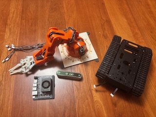
Here are our parts as of now:
In addition to our technical design progress, we also considered public health/safety/welfare, social, and economic factors related to our system this week.
Jasmine) From a public health, safety, and welfare perspective, because the robot includes a drivetrain and robotic arm operating near humans, we are prioritizing stable mechanical design, proper weight distribution, and controlled motion to reduce risks such as tipping, dropping objects, or unintended collisions. We plan to control the maximum motor speeds so that any accidental contact with a human or surrounding objects will not cause dangerous impact forces. We will also include software safeguards such as stopping the robot if unstable motion is detected and requiring confirmed object detection before the arm begins lifting. From a welfare standpoint, the robot assists users by retrieving and delivering objects directly to them, reducing physical strain and improving accessibility for people who may have mobility limitations.
Matthew) A few social factors that we have considered is how different cultures react to relying on technology and robots. For example, some western countries like the U.S. are often scared of robotics and technology replacing humans in terms of employment. Although having a robot do certain tasks might be more efficient and error free, some view it as taking away somebody else’s job. That being said, some other countries like Japan have embraced robotics and integrated them into their society. For example, Japan has robotic hotel receptionists, restaurant servers, and even shopping mall guides. For our project, we could potentially be replacing caretakers, as some elderly individuals may often hire someone to bring in groceries for them. At the same time, if an elderly person were to replace their caretaker with our robot, they may overlook other advantages that the caretaker had. For instance, an elderly person may be able to socialize more with humans if they have a caretaker, as opposed to living in a more isolated environment with just robots. Because of this possibility, we plan to have our robot not replace caretakers, but simply handle a small task that would be inconvenient for both caretakers and the people they are caring for. Our robot will be built to serve alongside the caretaker, so they can focus on other more pressing tasks.
Joon) From an economic perspective, our design prioritizes the use of commercially available off-the-shelf components such as the Arduino Braccio robotic arm, the Jetson Orin Nano embedded computer, and the Intel RealSense Depth Camera D435i. These components are reasonably priced, reliable, and easier to replace if needed, which reduces development cost while making the system easier to maintain and reproduce without requiring custom manufacturing. Because the robot is intended for common household assistance tasks like carrying groceries or boxes, using widely available hardware also improves the practicality and scalability of the system for real-world deployment. Additionally, we are structuring the robot as a modular system so that mechanical, computing, and control components can be upgraded or replaced independently. This modular approach helps manage long-term costs while allowing the system to adapt to different use cases or hardware improvements over time.
Feb 1 – Feb 7
Currently, the most significant risk that could jeopardize the success of the project is the mechanical implementation of our robot. We believe there is sufficient documentation and tools available to handle the software required to control our robot, but designing and integrating an elevator or arm system onto our drivetrain will be challenging.
To manage this risk, we plan to offload as much mechanical engineering as possible to suppliers. This approach will involve purchasing off-the-shelf robotic arms and grippers and fine-tuning them to reliably pick up objects such as a wallet.
If our budget allows, we plan to purchase multiple arms so that we have a backup design in case our primary arm or gripper does not work as expected.
A major change to the existing design was switching to an arm-based delivery system. After presenting our initial ramp-based use case, our advisor expressed concerns about feasibility and accessibility for users. After discussing alternatives, we decided it would be more effective to raise the object directly using an onboard arm mechanism. This change was necessary because it improves accessibility for users and removes the need for them to travel to a specific ramp location to retrieve items, making the robot more practical and assistive.
Despite this design change, our team remains on schedule. The decision to transition from a ramp system to an arm mechanism was made early enough in the design process that it does not significantly impact our overall timeline. Instead, it shifts our focus toward mechanical integration and component selection earlier in the semester. Our team has already begun researching potential arm and gripper solutions and evaluating compatibility with our drivetrain and computing system.
We also made progress in securing key components for the robot. We have obtained a drivetrain base, Jetson Orin Nano, and a depth camera, which will support our perception and control pipeline. Establishing these core components helps solidify our system architecture and allows us to begin planning subsystem integration and testing.
Moving forward, we plan to focus on finalizing hardware selection and preparing for the design presentation. We will continue evaluating arm and gripper options, begin integration planning, and submit remaining part requests. These steps will help ensure that we can transition into prototyping and testing during the next phase of the project.