Team Status Report for 04/26/2025

This past week has been spent working on optimizing the height map to 3D model algorithm and finishing upgrades to the manipulator. All that’s left to do is characterize the limits of our system and gather data that compares our scans to a traditional 3D scanner’s.

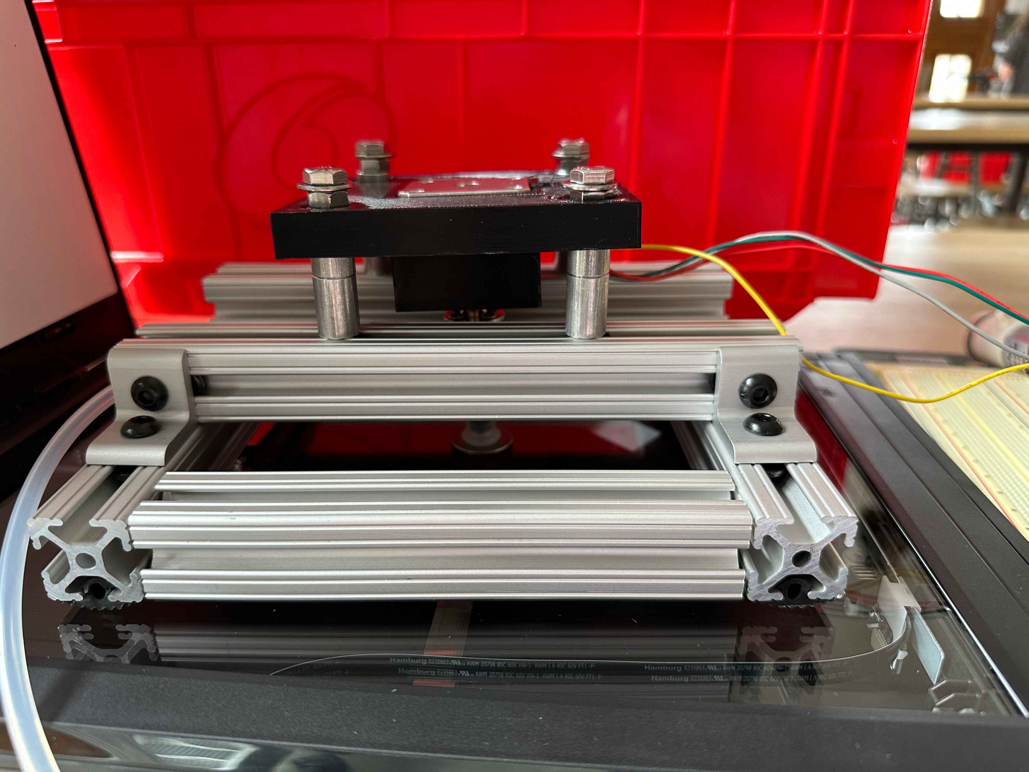
Theo finished the linear bearings upgrade to the manipulator and has made a new design for the electronics housing.

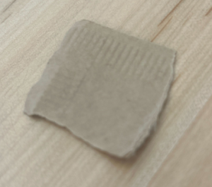
Yon worked on printing some parts including the test object, and writing the object comparison algorithm.

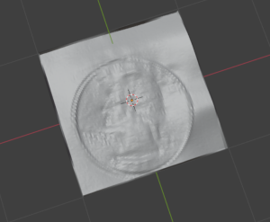
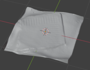
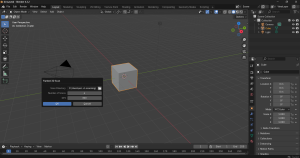
Sophia started testing and bug-fixing code for the automatic import of the height map into an object in Blender. So far it creates the plane, but it’s having trouble to find the correct file path for the height map. It should be able to be fixed before the final demo, but worst case scenario it takes maybe a minute to manually create the plane and add the height map to create the object in Blender.

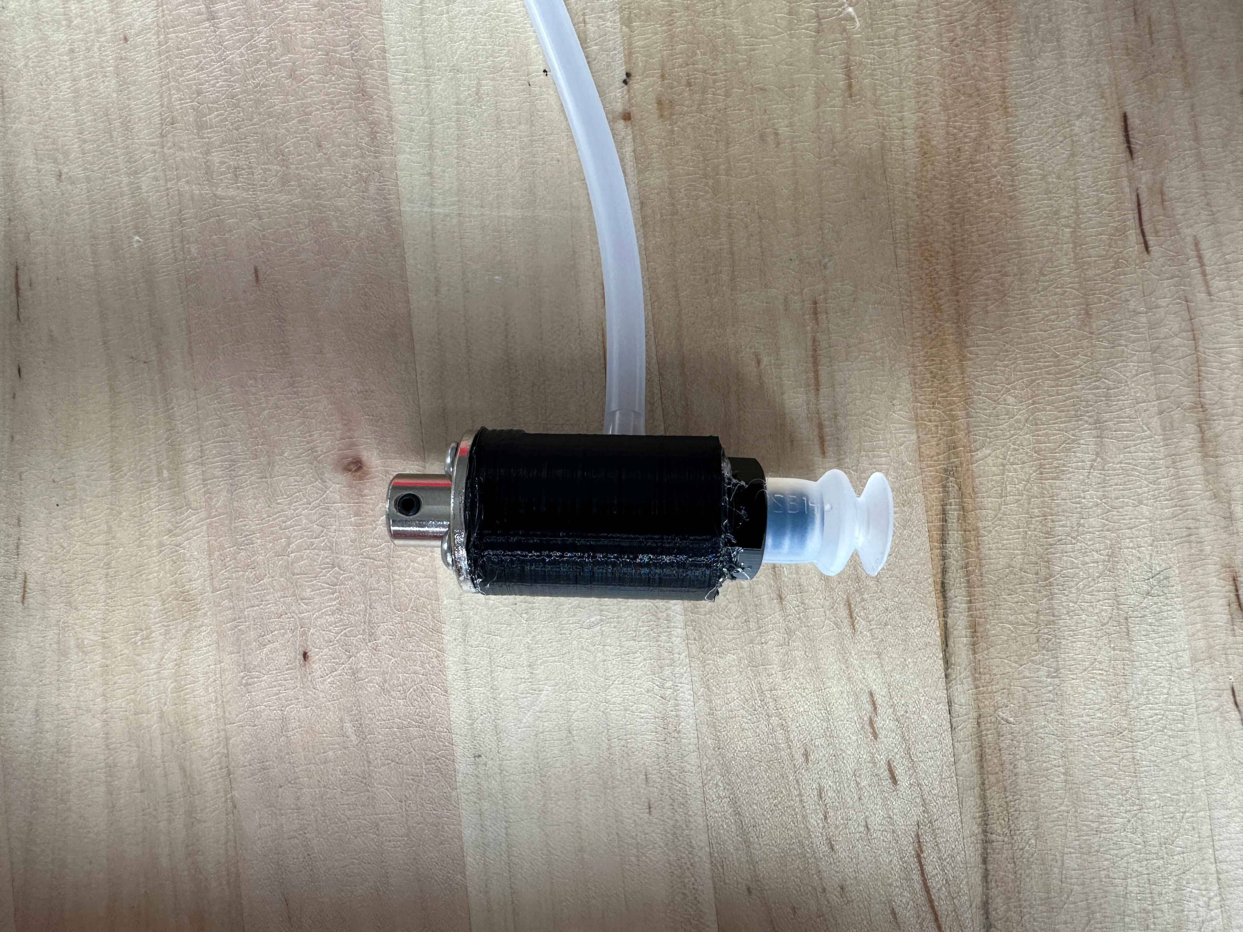
Unit tests for the manipulator included measuring out precise rotations and making sure the manipulator could be placed on and rotate objects of different heights and sizes. We’ll continue to test this through our system test.

There are two main areas of the image processing system that need to be tested: image alignment and model creation. Image alignment can be easily tested by running several different shaped objects through the system and ensuring the resulting bounding box represents aligned images. The model creation part is a little harder to test, and is the reason we Yon has been working on the test object and model similarity score algorithm, which will general a similarity score between our scan and the ground truth, along with a quality score comparing our scan with the benchmark scan of the same object. We can only really test this on an object for which a ground truth exists, so this won’t exactly be a ‘unit test’. We will also run scans on a variety of different objects and perform a visual inspections on them.

Unit tests for the software include running the files individually to make sure they completely worked before adding another file to the system pipeline. Ex. we ran the dotNet C file (which runs the scanner) first many times, then ran the Main.py file which would include running the dotNet file, then running the align file repeatedly to  make sure it works, then added in the align file to Main.py and ran it many times to make sure it works, etc. So it was an iterative process of running individual files, then adding them to the system after they’ve shown they worked individually, then running the system to iron out integration.

Our overall system test consists of:

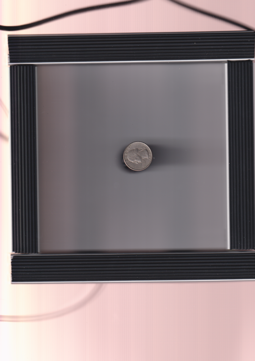
  1. Place object on scanner
  2. Place manipulator on top of object
  3. Plug in manipulator and scanner to user’s computer (both USB)
  4. Run project script. The system alternates between scans and rotations until the object has been rotated around to its starting position.
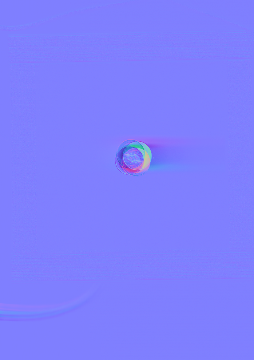
  5. The image processing automatically derives the normal map of the object and then generates a height map.
  6. The height map is imported to Blender for the user to inspect and interact with.

The only work from the user is during the setup. After starting the script, it only takes a minute or two (depending on the DPI of the scan, a modifiable parameter) for the object to be viewable in Blender.

Sophia’s Status Report for 04/26/2025

This week I started testing and bug-fixing the automatic import of the height map into Blender through the Blender add-on.

I figured out how to pass the number of the scan ID back to the Blender add-on, because that’s originally found in the Main.py file that’s run as a subprocess, so we can make sure we grab the right height map from the right folder.

There’s some bugs around directory changing and getting the right file path for the height map to import it, but I think it can be ironed out before the final demo. Worst case scenario, it takes a minute maybe to manually make the plane and import the height map to make the object.

Theo’s Status Report for 04/26/2025

This past week was spent on putting the finishing touches on the manipulator. We installed the new mount, linear bearings, and longer screws+spacers. The resulting mechanism is extremely smooth, and capable of fitting objects as thick as the frame’s space allows. The last thing that needs to be fixed up is the mounting. The motor shield on the ESP32 board makes designing housing around the outgoing wires difficult, but this next iteration ought to work. Functionally, the manipulator is complete. Besides the 3D print, all of my remaining time will be spent helping characterize the manipulator, gathering data, and working on our reports.

Theo’s Status Report for 04/19/2025

This past week was spent designing and implementing upgrades for the manipulator hardware. The linear bearings arrived, so I made a mount to fit them and used M5 screws, spacers, and nuts to accommodate them. The motion is very smooth and stable, but the thicker mount takes up the majority of the 1.5″ clearance the current screws allow. I’ll swap out the screws with 3″ long ones this upcoming week.

The electronics housing is the other piece I’ve been working on. The current design ought to work: it fits the microcontroller and DC air pump inside of a 3D-printed shell that clicks together and can be screwed onto one of the T-channels that make up the manipulator.

Functionally, the manipulator is fine. This last bit of upgrades should give us the full capabilities we planned for. After this, most of my time will be spent helping the others improve the image processing or user interface.

On learning new knowledge:  I started using a new CAD software called OnShape during this project, which had a bit of a learning curve but ended up being faster and easier to use than SolidWorks. I found it was easiest to keep a tab with the documentation open while working so I could quickly find solutions for any problems I had. I also got to learn a lot about the math behind our computing of normal maps, height maps, and 3D objects. Most of this was learned from Yon explaining it and our group reading through the relevant papers together.

Sophia’s Status Report for 04/19/2025

This week, Yon and Theo got alignment working pretty well, so I integrated it into the system pipeline. It occurs after the scans are taken, but before the normal map is done to ensure that the normal map itself is all aligned properly.

Since the normal map and height map were then sorted out, I figured out how to get a height map as an object in Blender. I did this first through a tutorial using the Blender UI, adding in a plane object, giving it a material, and uploading the height map. By adjusting the “strength” you can get the height differences to be more or less significant and more accurate to what the real-world object is.

Here are the models for a regular quarter coin and a piece of paper (along with the real-world photo of a piece of paper) that we got from manual height map uploads with a DPI of 100.


After those successes, I also wrote code to automatically do this process in Blender, so after pressing the Flatbed 3D Scan add-on button, a few minutes later you would have the object itself in Blender with no other work. I’ll be testing this first thing next week.

Next steps would be to ensure the automatic object creation works and to see if there’s any way to crop the height map or Blender object to only where the actual object is, so we don’t end up with blank white space on the edges of the models. Yon also has his own normal to height map file algorithm that we are going to try and compare with the one I used from another Blender project, so we can figure out which works better and/or faster.

To be able to accomplish the tasks I’ve done through the project, I mostly used online research, tutorials written and from YouTube, and lots of Stack Overflow posts to learn. Some things I had to learn specifically were how to set up and use a Dotnet project, how to use subprocesses, and navigate file directories to run all of these different files properly. I’ve had to learn a lot about Blender add-ons and the Blender library,  also how to use Blender itself because the UI elements translate almost directly over into the Blender library.

Team Status Report for 04/12/2025

This past week, the most significant problems we’ve encountered have been with the quality of the scans. As mentioned in Theo’s status report for this week, the stepper-suction adapter casts a black shadow behind the object that shows up in the normal map, and the rotation is still misaligned. The new mount has tighter tolerances that prevent it from sliding around, but it is still extremely difficult to place the suction cup directly in the center of the object (in order for each vector in the normal map to align). We’ve 3D printed a white stepper-suction adapter to see if that will help (it ought to blend in with the white acrylic cover sheet), and we’ve started looking into a software-level solution to the scan alignment issue. As detailed in Yon’s status report, we have two approaches to solve the alignment issue which we will test this coming week. These create very minor changes in our system, by introducing a small amount of complexity in the ‘image alignment’ step. If the image alignment goes well and creates better normal maps, we will then be able to move on to ensuring the height map turns out well, since the results are currently skewed from the misaligned normal map. There is a normal-to-height-map module currently as detailed in Sophia’s status report, but we may need to look for alternatives or edit it for our use case of small objects, since this module was normally used on larger cases.

As we continue to improve the manipulator, we’re also looking to begin testing with objects other than a quarter. Yon has designed a test object that we can start using when we’re ready, and the manipulator ought to be able to work with any object that fits in its 6inx6inx1in space. This also would be the validation of our system as a whole. When we compare the scan we take from the model, the original model we made, and the scans that commercial 3D scanners take, we will be able to calculate how close our scans are versus commercial scans using Hausdorff distance.

A scan from our current system and a normal map generated from it and its rotated counterparts. 

Sophia’s Status Report for 04/12/2025

These two weeks, I added in a pop up UI window for the Blender add-on. After you press “Flatbed 3D Scan” in the menu, a window appears where you can select the file path (should be where you store Main.py and other files needed), input the number of scans to take (min of 3 and max of 12, but this isn’t supported in the normal map calculations yet), and the DPI for the scans to use (fully functional).

I also found an existing Blender add-on “DeepBump” that had a module to convert a normal map to a height map. I utilized some of the code and put it into our project to use. It currently is part of the overall system run and produces a height map, though not a very good one because of our alignment issues. We may need to look for a different height map method depending on how well it works on an aligned normal map. This one seems to utilize gradients from the normal map in the Frankot-Chellappa algorithm, but as our project focuses on very small objects, I’m not sure a gradient is the right way to go.

Verification so far has included mostly manual testing of running parts of the software system and ensuring they’re working  by running an individual file I worked on, then run it using Main.py, then run it using the Blender add-on, etc. It’s difficult to set up unit testing since many of the functions depend on external signals, image file outcomes, and what the physical hardware does, so running it plugged in usually provides a good idea. Checking that files are saved appropriately and investigating when there is a crash or error has so far led to getting a functioning software subsystem. Future verification for image alignment would be manually checking the files to see if they have properly aligned the object. Verification for the height map would be a visual check of if the height map looks accurate to what we’d expect from the scans. Importing it to Blender would utilize Blender’s built-in errors as well as a manual check of the files, seeing that the .obj is created and appears in the Blender editor. We also run all of these manual tests on Theo’s computer, testing them on a different system (so we ensure it works on systems other than mine and I didn’t build it to something specific to my machine) and on the Linux OS with his dual-boot laptop.

The next step would be to align the images, ensure the height map is accurate enough, and then figure out how to import it into Blender as an .obj.

Theo’s Status Report for 04/12/2025

This past week, I’ve spent most of my time working on the manipulator hardware. We 3D printed a new mount with tighter tolerances, and it’s done a good job at minimizing the mount’s movement. The tight tolerance makes it hard to slide up and down, so we’ll probably use the linear bearings in our next upgrade (they arrived this Friday). We also laser cut the acrylic sheet and used it while scanning. It does a decent job at blocking out the noise from the air tubing, but makes it much more difficult to align the suction cup on top of the object (even more so when trying to center it). The current issues with our manipulator are off-center scans and a shadow being cast by the black stepper-suction adapter. We’re reprinting the adapter in white so it can match with the cover sheet, and we’re looking into making the acrylic cover sheet thicker. We have an extra 1/8″ sheet that we can cut identically and lay on top.

Here’s what a single scan in the current process and the generated normal map look like. The black shadow behind the object is entirely due to the stepper-suction adapter.


Team Status Report for 03/29/25

This past week was focused on testing the integration of our subsystems. We continued working on the Mac incompatibility issue but haven’t made progress yet. We’ve tentatively pushed it to the back of our task list, since it’s the least essential thing we’ve yet to do.

While Theo completed the manipulator and started testing for any issues, Yon and Sophia implemented the mapping code with the current control code. We were able to run a test where we ran an entire “scan,” with one of us rotating a coin on the scanner between each scan. Even with imprecise rotations and a scanner DPI of 100, we still observed decent a output map. Since the manipulator is completely working (besides some upgrades and adjustments mentioned in Theo’s status report), we will be ready to integrate everything we have so far on Monday.

We are still on track, with the next steps being to characterize and improve the manipulator while implementing our code in a blender plugin.

Theo’s Status Report for 03/29/25

This week was mainly spent working on the stepper-suction adapter, which would allow the suction cup to rotate with the stepper motor while still being connected to the air pump. It worked on its second iteration, and we were able to put together the entire manipulator. The suction and rotation work as desired, but we’ve yet to fully characterize what is and isn’t possible. All that’s left to do before demo day is make sure the delays in our serial python code are properly sized to let the entire physical rotation/suction happen. We’ll be able to do this within a few minutes on Monday.

I noticed with some of my first tests that the mount can become slanted on the guide pillars, which makes sense because those holes did not print out to the exact proper size. Rather than trying to get this right, I’m leaning toward implementing linear ball bearings that would function identically to the holes, but be properly sized, smoother, and sturdier than just a hole in our 3D print. I’ll order these on Monday.

The suction cup also sticks out relatively far down the manipulator, pushing the mount up the majority of the guide pillars that we planned to leave as slack/space for thicker objects. While this isn’t a point of failure, the remedy is as simple as having the stepper motor’s mounting hole stick less far down from the mount. Since we’ll be reprinting to ensure the linear bearings will fit anyways, one more print should solve both problems at once.

I’ve also continued work on the 3D-printed electronics housing that will be attached to the structure of the manipulator, but that is my last priority at the moment.

The two pictures attached below are the suction cup with the stepper-suction adapter, and the complete prototype demonstrating a slanted mount while resting on top of a coin.