This past week was spent on putting the finishing touches on the manipulator. We installed the new mount, linear bearings, and longer screws+spacers. The resulting mechanism is extremely smooth, and capable of fitting objects as thick as the frame’s space allows. The last thing that needs to be fixed up is the mounting. The motor shield on the ESP32 board makes designing housing around the outgoing wires difficult, but this next iteration ought to work. Functionally, the manipulator is complete. Besides the 3D print, all of my remaining time will be spent helping characterize the manipulator, gathering data, and working on our reports.
Category: Theo’s Status Reports
The status reports from Theophilus Cockrell.
Theo’s Status Report for 04/19/2025
This past week was spent designing and implementing upgrades for the manipulator hardware. The linear bearings arrived, so I made a mount to fit them and used M5 screws, spacers, and nuts to accommodate them. The motion is very smooth and stable, but the thicker mount takes up the majority of the 1.5″ clearance the current screws allow. I’ll swap out the screws with 3″ long ones this upcoming week.
The electronics housing is the other piece I’ve been working on. The current design ought to work: it fits the microcontroller and DC air pump inside of a 3D-printed shell that clicks together and can be screwed onto one of the T-channels that make up the manipulator.
Functionally, the manipulator is fine. This last bit of upgrades should give us the full capabilities we planned for. After this, most of my time will be spent helping the others improve the image processing or user interface.
On learning new knowledge: I started using a new CAD software called OnShape during this project, which had a bit of a learning curve but ended up being faster and easier to use than SolidWorks. I found it was easiest to keep a tab with the documentation open while working so I could quickly find solutions for any problems I had. I also got to learn a lot about the math behind our computing of normal maps, height maps, and 3D objects. Most of this was learned from Yon explaining it and our group reading through the relevant papers together.
Theo’s Status Report for 04/12/2025
This past week, I’ve spent most of my time working on the manipulator hardware. We 3D printed a new mount with tighter tolerances, and it’s done a good job at minimizing the mount’s movement. The tight tolerance makes it hard to slide up and down, so we’ll probably use the linear bearings in our next upgrade (they arrived this Friday). We also laser cut the acrylic sheet and used it while scanning. It does a decent job at blocking out the noise from the air tubing, but makes it much more difficult to align the suction cup on top of the object (even more so when trying to center it). The current issues with our manipulator are off-center scans and a shadow being cast by the black stepper-suction adapter. We’re reprinting the adapter in white so it can match with the cover sheet, and we’re looking into making the acrylic cover sheet thicker. We have an extra 1/8″ sheet that we can cut identically and lay on top.
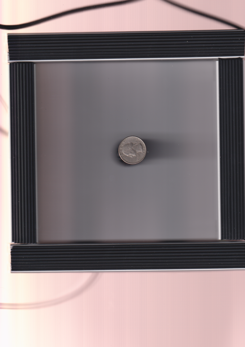
Here’s what a single scan in the current process and the generated normal map look like. The black shadow behind the object is entirely due to the stepper-suction adapter.

Theo’s Status Report for 03/29/25
This week was mainly spent working on the stepper-suction adapter, which would allow the suction cup to rotate with the stepper motor while still being connected to the air pump. It worked on its second iteration, and we were able to put together the entire manipulator. The suction and rotation work as desired, but we’ve yet to fully characterize what is and isn’t possible. All that’s left to do before demo day is make sure the delays in our serial python code are properly sized to let the entire physical rotation/suction happen. We’ll be able to do this within a few minutes on Monday.
I noticed with some of my first tests that the mount can become slanted on the guide pillars, which makes sense because those holes did not print out to the exact proper size. Rather than trying to get this right, I’m leaning toward implementing linear ball bearings that would function identically to the holes, but be properly sized, smoother, and sturdier than just a hole in our 3D print. I’ll order these on Monday.
The suction cup also sticks out relatively far down the manipulator, pushing the mount up the majority of the guide pillars that we planned to leave as slack/space for thicker objects. While this isn’t a point of failure, the remedy is as simple as having the stepper motor’s mounting hole stick less far down from the mount. Since we’ll be reprinting to ensure the linear bearings will fit anyways, one more print should solve both problems at once.
I’ve also continued work on the 3D-printed electronics housing that will be attached to the structure of the manipulator, but that is my last priority at the moment.
The two pictures attached below are the suction cup with the stepper-suction adapter, and the complete prototype demonstrating a slanted mount while resting on top of a coin. 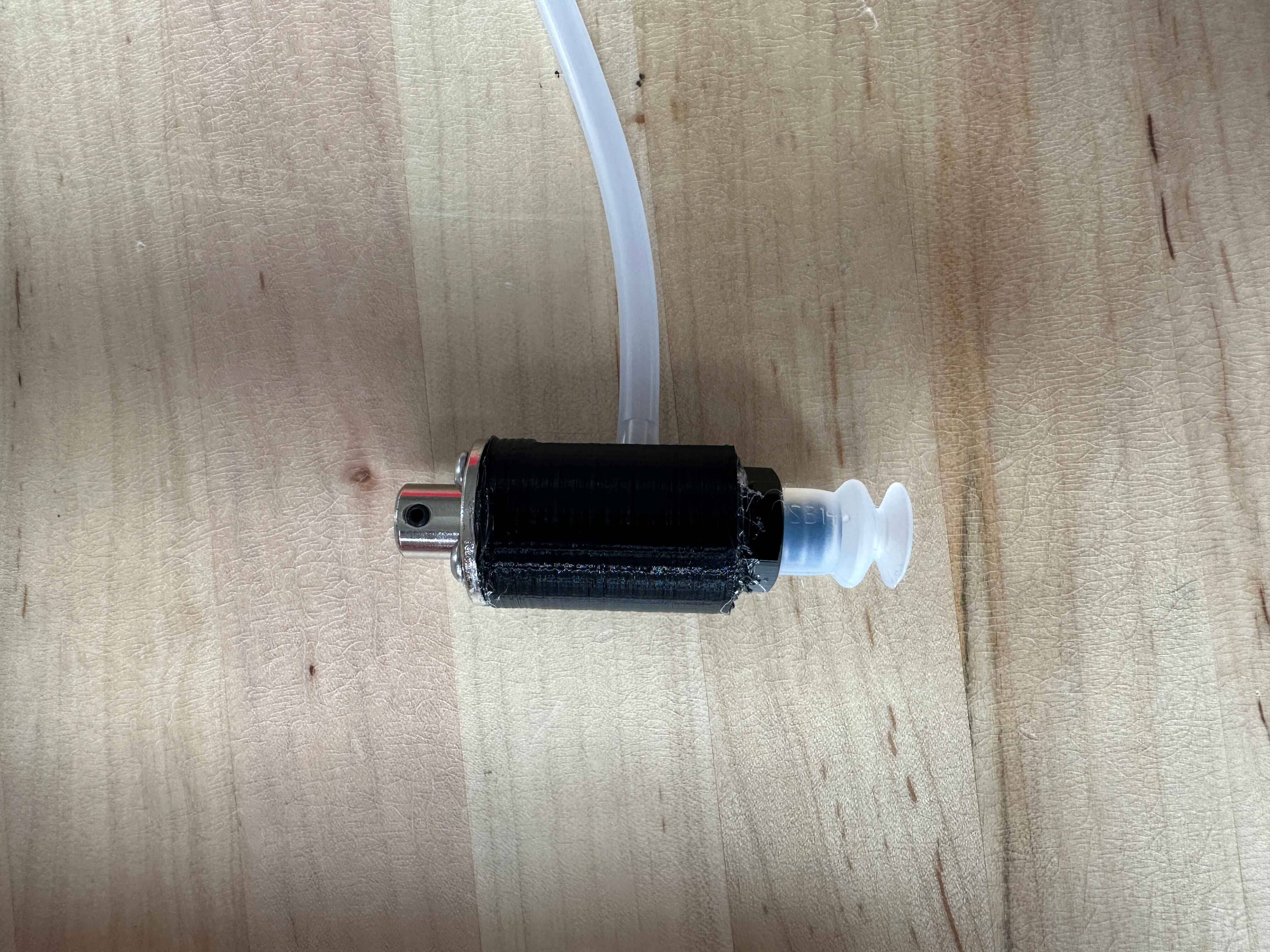
Theo’s Status Report for 03/22/2025
This past week was mainly spent working on the 3D printed parts for the manipulator. The newest iteration of our mount finally got the hole size right, so it slides up and down relatively smoothly. It will be interesting to see how well it works once the suction cup is attached to the stepper motor.
The adapter for the suction cup and stepper motor is going along well. It seems like there’s enough clearance in the area that we don’t need to cut the stepper motor axle. The next iteration needs to be longer and have a slightly larger hole for the suction cup, but it should be doable. I’ll have the stl to Yon by Monday for more testing.
The last 3D printed piece I’ll be working on is electronics housing. It will be a long box along one of the T-channels on the frame, housing the mirocontroller and dc air pump. There will be a micro-usb port and a 12V DC adapter port. I’m leaving this for last once we confirm full functionality for the manipulator itself.
Everything is still on schedule, hopefully the adapter doesn’t take too many iterations to finish. It prints pretty quickly (40min), so I may spend an afternoon in our 3D printing area to prototype and get it right.
Theo’s Status Report for 3/15/2025
This past week I focused on implementing the suction cup for our manipulator and helping Sophia debug the NAPS2 code we’re using to talk to our scanner. We’re able to toggle the suction cup on and off and have succeeded in lifting objects as heavy as my phone. With a t-connector, scissors, and hot glue, I was able to create a right-angle connection between the suction cup and the air tubing running to the pump. From here, we just need a 3D-printed piece that connects to a bearing on the stepper motor and aligns the suction cup with the shaft. I’m already working on its design, and we should have it 3D-printed by Wednesday. The stepper motor shaft will also need to be cut to accommodate this; I’ve already talked with the TechSpark machine shop, and we are able to make this cut anytime this week.
Theo’s Status Report for 3/08/2025
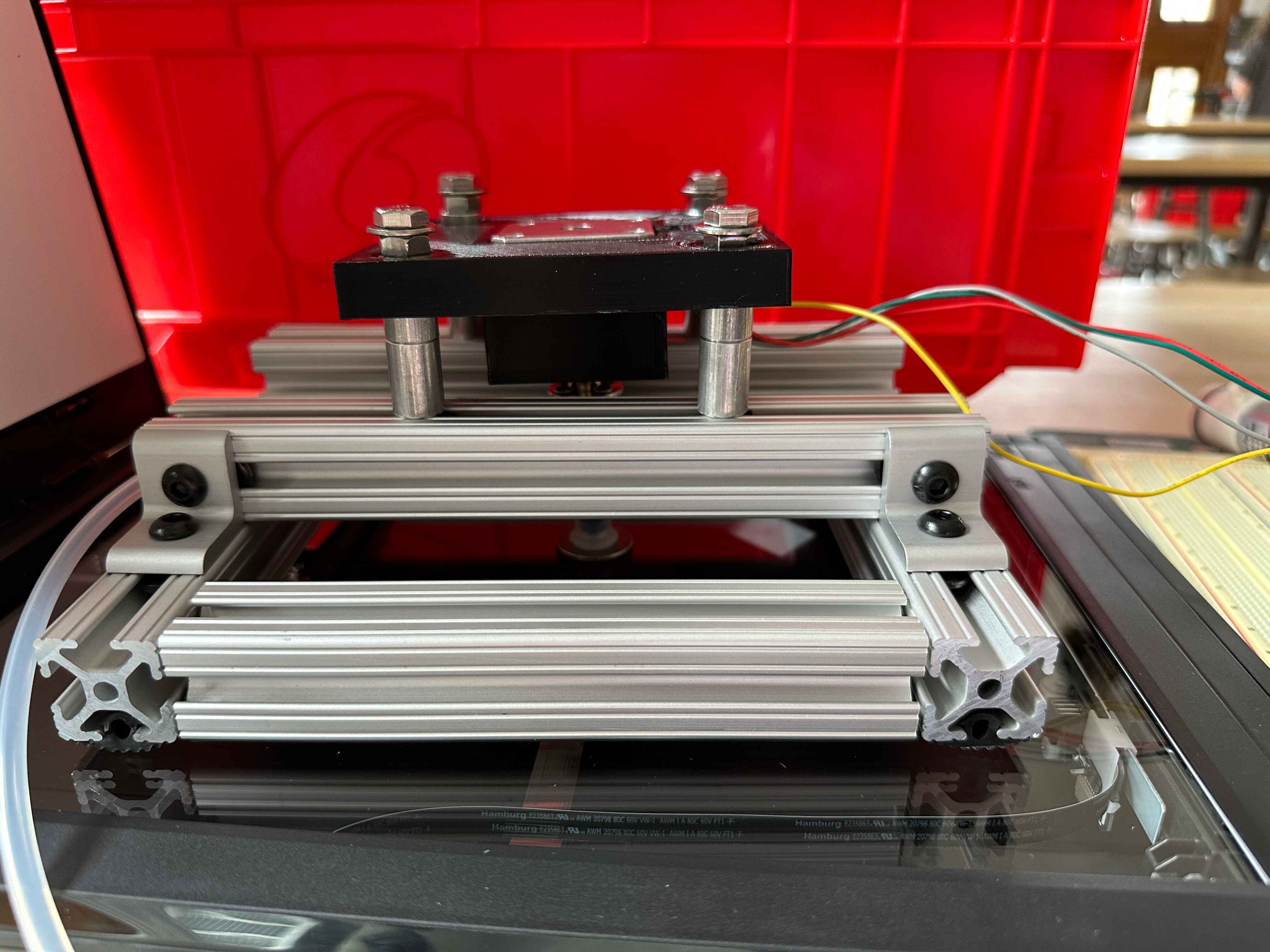
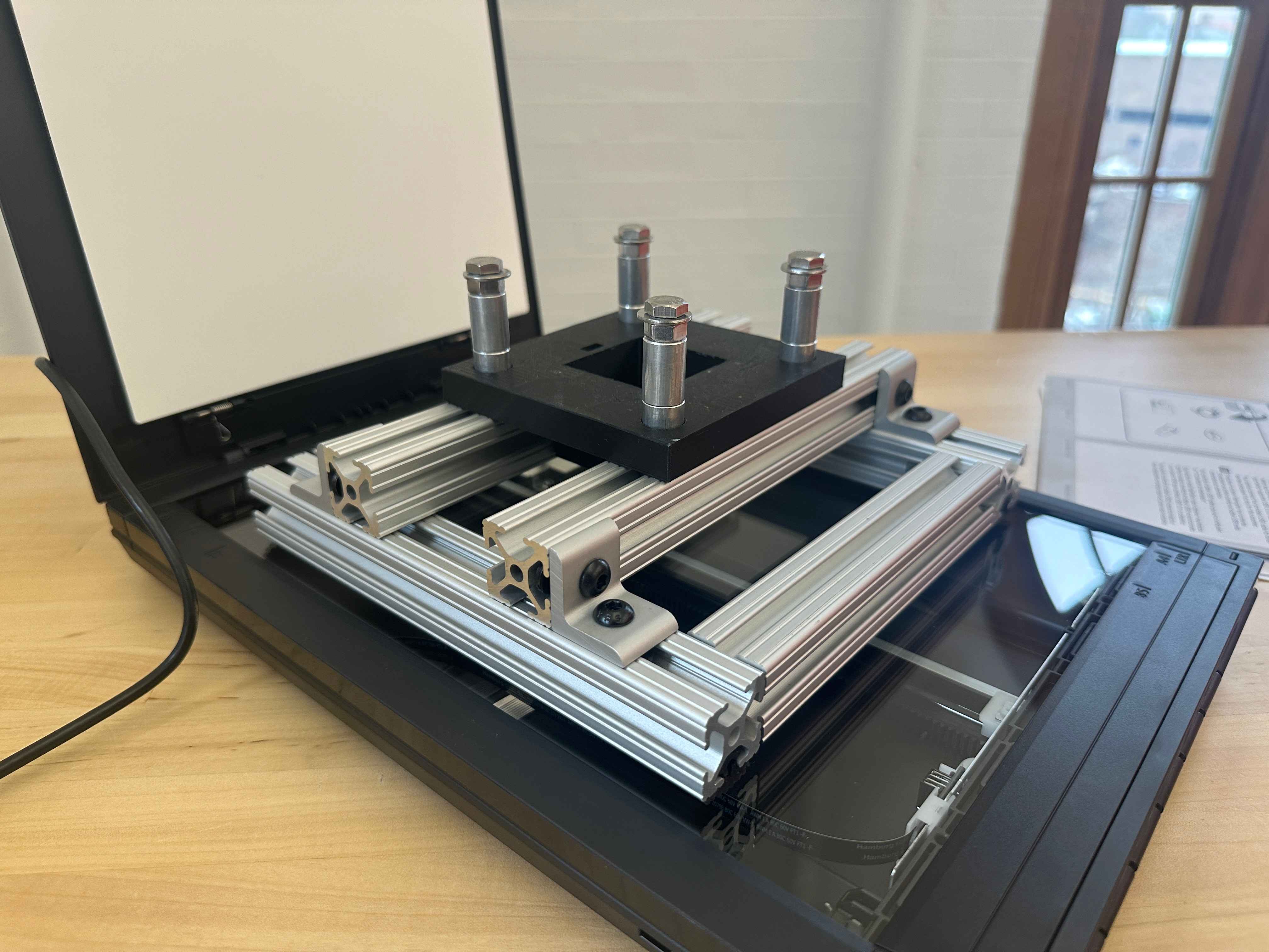
I’ve taken the past week off for Spring Break since I’m on schedule. The week before, we received the parts for the manipulator’s structure, so I actually built it (see image below). The parts all fit together besides the 3D printed mount, which needs slightly larger holes for the stepper motor to fit inside. We’ll 3D print this when we return to campus. So far, we’ve noticed slight instability and rough motion when trying to move the 3D printed mount up and down the screws with spacers. If the next iteration’s larger holes don’t enable the smooth and stable motion we want, then we’ll look into linear bearings or something similar.
We’ve also further theorized possible solutions to picking the object up during rotation. Currently, solenoids on the mount that push off of the second layer of T-channel extrusions is our best idea. This would likely work, and we would use at least two in order to deliver equal/symmetric force while sliding up the screws.
My next steps include finishing the troubleshooting on this 3D print, helping Sophia with integrating my basic serial test code with her control software, and designing + optimizing the 3D printed shaft-suction cup piece that we’ll use to connect the vacuum pump tubes and the stepper motor to the suction cup.
Theo’s Status Report for 2/22/2025
This week, I practiced more for my presentation before presenting on Wednesday and spent time figuring out the suction cup’s connection to the stepper motor. I found a shaft coupler that doubles as a mounting platform, to which I’ll attach a 3D printed mount for the suction cup that allows it to be rotated by the stepper motor while connected to the air pump. I ordered this, along with some more air tubing connectors and 3mm mounting screws (our stepper motor didn’t come with any), in our second amazon order. Our first amazon order and our adafruit order came in later this week, and I picked them up along with the 3D printed circuits mount (see electronics in github). The holes on the mount needed the slightest bit more clearance, so I added 0.25mm to the radius of each hole. We’ll 3D print it this weekend or next week.
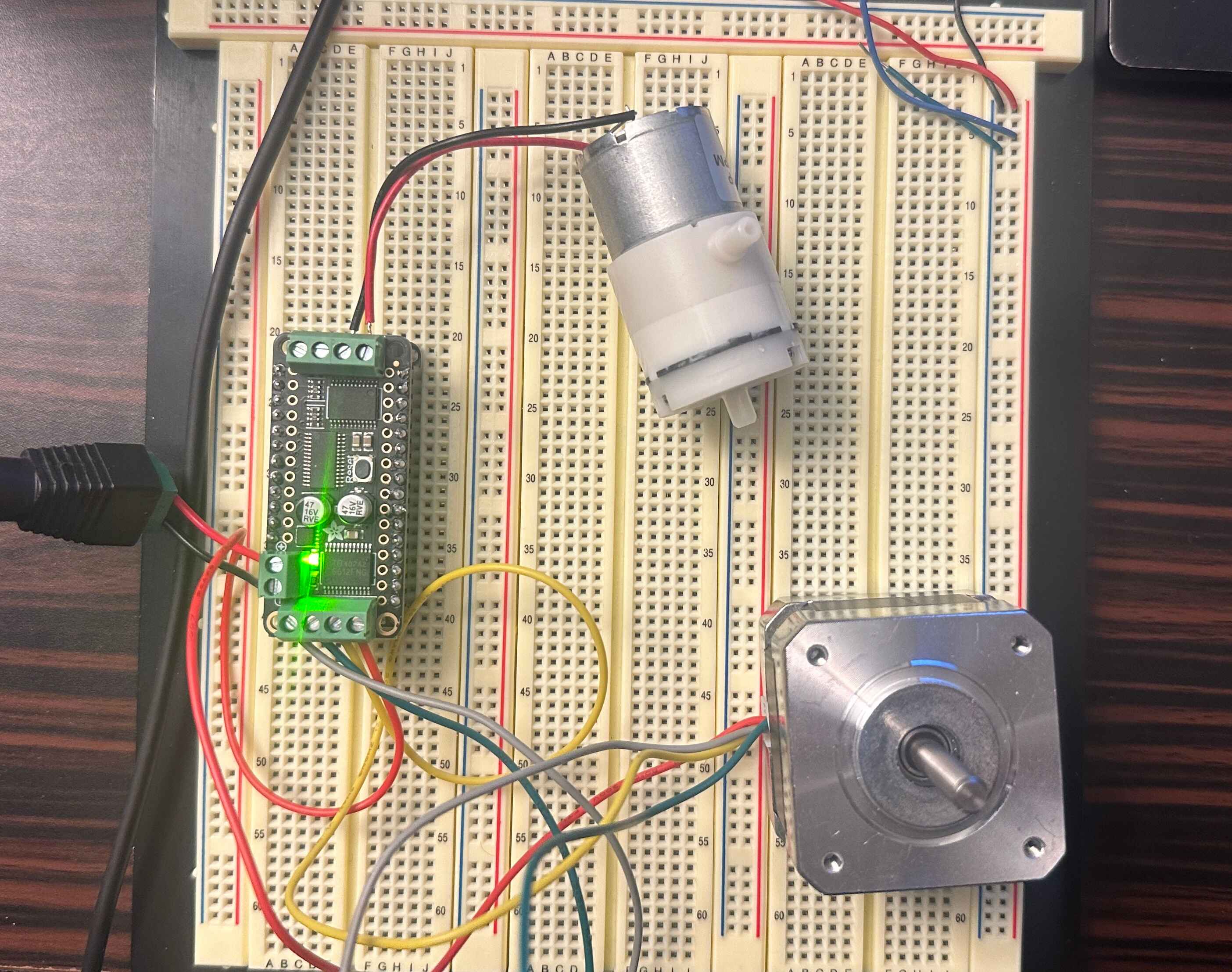
On Saturday, I started prototyping with the electronics that had come in from Adafruit and was able to control the stepper motor and air pump over serial. I’ve attached a picture of the setup below. Now I’ll wait for our new 3D printed mount, the suction cup, and the rest of the structure/hardware to come in before building a complete prototype.
Theo’s Status Report for 2/15/25
This past week I prioritized finishing the manipulator design and ordering the parts. I also finished the CAD mockup, including the first prototype of a 3D printed mount for the electronics. It will freely move vertically on top of the manipulator to account for objects of different heights/thicknesses. I’ll 3D print this mount and test it once the ordered parts have arrived and the rest of the manipulator is put together.
Though I’m still behind on my tasks from the roadmap, a lot of future time was allocated to debugging the hardware, characterizing the working prototype, and designing a new version with a suction cup manipulator (instead of just a friction tip); this time may as well be slack time that’s instead used for this prototype. We’ve gone ahead and ordered the air pump, tubing, and suction cup with the rest of our parts. The suction cup is the same material and size (silicone for high coeff. of friction, 13mm diameter to fit behind a dime or similar coin) as we would’ve made the friction tip, so we will simply test the prototype with and without activating suction instead of needing to build an entirely new prototype/add-on. I believe this will be a massive time save, and don’t foresee any issues with the current design. I’ve uploaded the solidworks assembly+relevant files to github.
Besides working on the design and prototype, I’ve worked with my team on the design review presentation slides. I’ll be presenting on either Monday or Wednesday, and the tentative plan is to finish a draft early enough tonight or tomorrow so that our TA can look it over and give advice.
Theo’s Status Report for 2/08/2025
My work this past week consisted of helping with the proposal presentation and drafting a prototype + its CAD model. I was responsible for the hardware requirements, specifications, and solutions in the proposal, and helped with edits to the entire presentation in the time leading up to presentation day.
The CAD model is a few days behind schedule according to the roadmap. This is mainly due to me wanting to render the functioning linear actuator/lead screw, rotation motor, and microcontroller. I am still working on this model and have additional free time this week to catch up. The current prototype will be built out of 1-inch T-slot aluminum extrusions (CADing done with parts from 80/20), using an ESP32 dev board capable of operating a motor driver and at least one stepper or servo motor. I am still weighing the pros and cons of a linear actuator vs a manual lead screw, as well as a stepper motor vs a servo motor. The circuit will likely need an external power supply to power any of these motors, since the traces on an ESP32 won’t handle the power necessary to keep the motor powered over an extended period. This should all be resolved and the parts can be ordered by the end of next week. Though this places the hardware behind schedule, I am not worried. Assembly will be simple and can be done the day the parts arrive, and all should be back on track after that; the characterization task that comes after assembly should really only take a day or two, and the programming itself will be simple motor control. There is plenty of slack time in these first few hardware tasks that allow for this setback.
I’ve started on a basic arduino program for controlling the ESP32 and testing the stepper motor system’s accuracy. One of the first things we’ll be testing once we have the ESP32 is our ability to send it commands from our project’s software. If the arduino IDE/language doesn’t work, MicroPython is the next most likely route of hardware programming.