Nathalie’s Status Report for 4/27

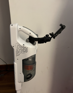
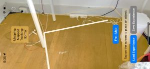
Testing the Bounding Box of the Vacuum Camera

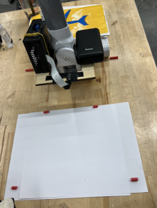
In order to properly track the segments and label them, I set up an experimental testing process that would allow us to calibrate the camera’s field of vision. I set up the vacuum system on a table in Techspark and created little red rods to delimit borders of its field of vision. By accurately determining these parameters,  my goal was to refine the precise cropping and granularity in our image capturing. Then we ran scripts to see what the camera was outputting,  making sure that the red straws were in the corner of the frames. I found that our initial cropped camera vision was too small compared to the range that the camera could actually capture. Our group performed several iterations of this testing to get accurate measurements so that we could translate this to the XCode/iPhone side of things. I measured the distance of the box length to be 19cm, distance from the beginning of the box to the handle to be 12cm, the width of the bounding box to be 28cm.

Improving the UI for Enhanced User Experience

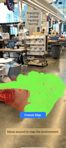
Recognizing the importance of user-friendly interaction, I refined the user interface of our system. While this continues to be a work in progress, I’ve been rewriting the messages and changing which features are displayed on the main page.  I still have to do testing with users and will be adding more obstructive coaching that forces instructions in front of the users faces (currently, it’s easy to dismiss and not read the directional instructions).  When demoing, one goal is to reduce our need to interfere with the user’s experience with the product.

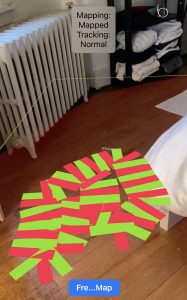
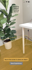
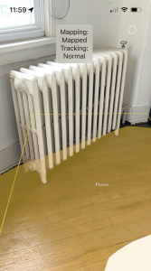
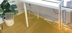
Implementing a Green Transparent Tracking Line

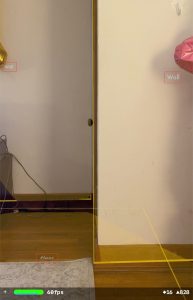
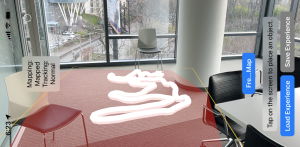
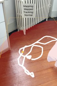
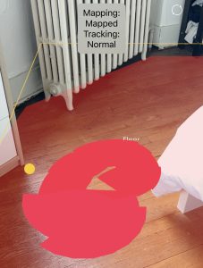
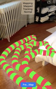
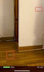
Now that we have our accurately drawn mechanisms in place, I decided to have an additional green line drawn from the back of the vacuum, indicating coverage irrespective of the back camera’s dirt detection. This transparent green line will update with red segmentation for spots that are marked as dirty. This feature provides users with real-time feedback on the vacuum’s progress, allowing them to monitor its trajectory and efficiency. The inclusion of this visual element not only enhances the user experience but also incorporates feedback mechanisms that empower users with greater control and insight into the system’s performance, ultimately leading to more efficient cleaning processes. The bounding box work has also been effective in allowing the traced green line to not extend beyond the initially mapped area. The picture below shows an example tracing of the green line that I created in TechSpark while testing. We can see texture of the red parts and the stripes in the lines, but I’ve modified it so that the green line appears under the red lines (so the red lines are more visible). I’ve also done work to calculate the proper width of the vacuum for coverage purposes, and adjusting the appearance of the green line as such.

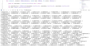
Troubleshooting Data Transmission Latency

As mentioned in the presentation this week, Erin, Harshul, and I worked together to try and figure out why Bluetooth latency was ~5s. This was a problem because there were more tracked times and coordinates that did not have an associated dirty/clean classification and therefore would be drawn green by default even when everything was supposed to be marked dirty. By printing times and calculating the latency of each instruction, we were able to locate the issue. At first, we thought it was the data transmission and the limitations of BLE that take a long time to send and and can only accommodate a certain amount of data. It turns out, it was actually the dirt detection script. The multi-second delay was attributed to toggling the Jetson camera on and off constantly. The reason why it was getting turned on and off was because there are compatibility issues between different Python versions needed for different parts of our scripts. Namely, the Nanocamera package only exists in 3.6 while the async calls needed for BLE exist only in 3.8. So we PIPE’d the camera in and found a way to work around this problem so that the camera was only turned on once at the beginning and once at the end.  While before we had a 5s delay in data, now it is essentially real time with data coming at ~0.15 seconds with potential for further increase. Through iterative testing and refinement, we aim to minimize latency and ensure seamless communication between devices, thereby enhancing the overall reliability and responsiveness of the system. We need to now record on the iPhone side the same number of data at the same frequency.

Hardware Mounting and Material Selection

I also worked on mounting hardware involved careful consideration of materials and techniques to ensure stability and functionality. We made sure to discuss the components that we may want to adjust or remove later, distinguishing between permanent fixation with epoxy and the components suitable for temporary attachment using hot glue and duct tape.  For example, we wanted the portable charger to be removable in case we need to charge or replace it, but used epoxy for the laser cut wood pieces to solidify them together. By selecting appropriate materials and techniques for each component, we have a solid mounting of components that meets the demands of our application.

Next Steps

Moving forward, I’m going to be working on integrating CoachView as part of the UI to further enhance usability and accessibility. Erin Harshul and I  are going to work together on trying to on refining timeQueue usage and pick the optimal data frequency, figure out the border/script granularity needed, and then conduct comprehensive system integration and testing. While getting the system ready for our demo, we need to simultaneously prepare for the final presentation, meaning that we need to work on our video, poster, and plan out how we are going to demo and organize our space.


Nathalie’s Status Report for 4/19

This week’s tasks

I spent this week working on integrating our AR components together: the image detection and tracking + offset for the back Jetson camera that we demonstrated  during our weekly meeting. This was a proof of concept that we could actually map the fixed area offset between our frontal camera positioning and the back of the Jetson using the airplane image. This image can be substituted out, but serves as a reference point. I’ve also sketched out the hardware laser cutting acrylic that needs to be completed for the mounts.

On top of that, I’ve been working on finding the optimal way to create a path. Our initial proof of concept was to use a SCNLine module type, which essentially draws a line on the plane. After further researching, I discovered another potential module type that we could use to indicate the covered area called SCNPath. The declarations are relatively similar, but they have different UI aspects and plane drawing memory capabilities. Specifically, SCNLine provides more granular control over individual segments of the path and draws the points in a single line, whereas SCNPath allows drawing of different segments which could be easier to color (the parallel task that I’m also working on). In the below images, you can see the differences between radiuses and width and the visual representation that it gives on the screen. I think I prefer the SCNPath visuals, but the backend itself and line management system is different.

Figure 1: SCNLine with a radius of 0.05
Figure 2: SCNLine with a radius of 0.01
Figure 3: SCNPath with a width of 0.02


I’ve also worked on drawing a path in order to indicate its level of dirtiness. To accomplish this, I delved into experimenting with various metrics of the SCNPath and SCNLine attributes. I found that it lacked some flexibility needed to retroactively modify attributes like color based on real-time data. By changing attributes within the materials of these node objects, we are able to the color of the path. These different colors are important because they are the user indication of the varying levels of dirtiness. I can easily change the different colors of the path but doing so in a patched-way (changing line segments, drawing different lines of different colors) has been more challenging than I expected.

Green color changes in SCNPath

As shown below, I’ve been able to edit the code such that it colors different segments and can capture the segmented floor, unfortunately, there seems to be some gapping betweent he segments when turning. This is demonstrated in the images below, but the effect is still present which serves our use case. I’m going to look further into how I can mediate those gaps going forward, but the positive side is that the coloring does not seem to affect latency.

Coloring with SCNLine
Coloring with SCNLine (2)
Coloring with SCNPath


In addition to path coloring, I worked closely with Erin and Harshul on hardware integration, designing our final mount for the vacuum and actually putting the pieces together. We worked a lot in TechSpark this week and have needed each of our subsystem pieces to make progress since we are in the refinements/mounting/integration stages of our process. I fixed some bugs with reference to the freezing plane logic, and also refined the UI to actually reflect the work that we are doing rather than what was part of our initial prototype.

Next Week’s Tasks, Schedule & Challenges

Harshul and I have been working with Erin to make sure that the Bluetooth part is making progress. Integration has been really difficult for us due to the setbacks from last week of the Jetson being broken, but we are trying our best to troubleshoot and make progress now that it’s been resolved. I need to polish up the path coloring logic, and connect that to the actual messages that are being received by the Bluetooth. This is really hard, especially because it depends on the Bluetooth connection integration actually performing, and the Bluetooth has not been as reliable as we had hoped. We got something working this week that needs to be fully flushed out and refined, so our next steps are defining specific test cases to actually test the accuracy of our mapped mount system.

In addition to the technical challenges we face with Bluetooth integration and hardware mounting, there are several other factors to consider as we move forward with our project. We planned the testing and validation of the integrated system, but need to actually perform this testing so that we can make sure our system performs as we had initially set out in our use case and technical requirements.. This includes testing the reliability of the Bluetooth connection under various dirt conditions and scenarios to ensure completeness, and making sure it can perform at a reasonable speed. To get this done, we need to collaborate and communicate as a team members to troubleshoot any obstacles that may arise along the way because we each had a hand in developing some part of a subsystem so all expertise is required.

Given the time constraints leading up to our final demo, it’s essential to prioritize tasks and allocate resources efficiently. This may involve making tough decisions about which features are essential for the core functionality of our system and making these decisions really quickly. This is evident in our hardware mount decisions which are designed specifically for the demo rather than an “industry standard” prototype. We have backup Bluetooth communication protocols and hardware configurations that may offer better performance or reliability, but are not the most optimal in terms of design and technical specifics.

Team Status Report for 4/6

Risks

One large risk that our group is currently facing is the fact that Erin is currently dealing with a number of issues regarding the Jetson. This is a large blocker for the entire end-to-end system, as we are unable to demonstrate whether the dirt tracking on the AR application is working properly if the entire Jetson subsystem is still offline. Without the dirt detection functioning, as well as the BLE connection, the AR system does not have the necessary data to determine whether the flooring is clean or dirty, and we will have no way of validating whether the transformation of 3D data points that we have on the AR side is accurate. Moreover, Erin is currently investigating whether it is even possible to speed up the Bluetooth data transmission. Currently, it seems that an async sleep call for around ten seconds is necessary in order to preserve functionality. This, along with the BLE data transmission limit, may force us to readjust our use-case requirements. 

Nathalie and Harshul have been working on tracking the vacuum head in the AR space, and they have also been working on trying to get the coordinate transformation correct. While the coordinate transformations have a dependency on the Jetson subsystem (as mentioned above), the vacuum head tracking does not, and we have made significant progress on that front. 

Nathalie has also been working on mounting the phone to the physical vacuum. We purchased a phone stand rather than designing our own mounting system, which saved us time. However, the angle which the stand is able to accommodate for may not be enough for the iPhone to get a satisfactory read, and this is something we plan to test more extensively, so we can figure out what the best orientation and mounting process for the iPhone would be. 

System Validation:

From our design report and incorporating Professor Kim’s feedback outlined an end-to-end validation test that he would like to see from our System below is the test plan for formalizing and carrying out this test.

The goal is to have every subsystem operational and test connectivity and integration between each subsystem.

Subsystems:

  1. Bluetooth (Jetson)
  2. Dirt Detection (Jetson)
  3. Plane Projection + Image Detection (ARKit)
  4. Plane Detection + Ui
  5. Bluetooth (ARkit)
  6. Time:position queue (ARKit)

With the room mapped with an initial mapping and the plane frozen, place the phone into the mount and start the drawing to track the vacuum position. Verify that the image is detected and the drawn line is behind the vacuum and that the queue is being populated with time:position points (Tests: 3,4,5,6)

Place a large, visible object behind the vacuum head in view of the active illumination devices and the Jetson camera. Verify that the dirt detection script categorizes the image as “dirty”, and proceed to validate that this message is sent from the Jetson to the working iPhone device. Additionally, validate that the iPhone has received the intended message from the Jetson, and then proceed to verify that the AR application highlights the proper portion of flooring (containing the large object). (Tests: 1, 2) 

Schedule

Our schedule has been unexpectedly delayed with the Jetson malfunctions this week, which has hindered the progress on the dirt detection front. Erin has been especially involved with this, and we are hoping to have it reliably resolved soon so that she can instead focus her energy on reducing the latency with regards to Bluetooth communication. Nathalie and Harshul have been making steady progress on the AR front, but it is absolutely crucial for each of our subsystems to have polished functionality so that we see more integration progress, especially with the hardware. We are mounting the Jetson this week(end) to measure the constant translational difference so we can add it to our code and do accompanying tests to ensure maximal precision. A challenge has been our differing free times in the day, but since we are working on integration testing between subsystem it is important that we all meet together and with the hardware components. To mitigate this, we set aside chunks of time on our calendars allotted to specific integration tests.

Nathalie’s Status Report for 4/6

I spent this week combining multiple features of the augmented reality component, specifically freezing the plane and tracking coverage metrics. In addition, I did initial scoping, researching and solidifying approaches for object detection, where picking a reference object that has a fixed distance with the back Jetson camera would allow us to locate the world coordinates of the Jetson camera at any given point. I performed initial testing of our floor mapping technology so that I could plan how to verify and validate our augmented reality subsystem going forward, making sure that we are able to track coverage and integrate our individual functionalities without compromising on latency.

Floor mapping with tracking based on camera middle point and present objects in a non-rectangular space

Integrating with physical components

As I have been working on the augmented reality app, I am familiar with how it works and got the opportunity to experiment with the placement of our components because we finally received the phone mount that we ordered. I spent the early parts of this week playing with object detection in order to orient a specific object within world coordinates, and needed some physical metrics in order to inform the approach that I am going to take with reference to object detection in the AR front. Essentially, mine and Harshul’s goal (and what we are currently working on) is to detect a specific object in the space which serves as a reference point on the front of the vacuum, from which we can map the constant translational difference from the front of the vacuum to the back where the Jetson camera exists. Initially, I had thought (and we expected) to mount the phone mount on the actual rod of the vacuum. When I actually assembled the components together and put the mount on the handle with the phone + AR app mapping the floor, I realized it was too close to the ground so wouldn’t provide a user-friendly aerial view that we had initially envisioned. From initial validation tests, the floor mapping technology works best when it has the most perspective, as it is able to interpret the space around it with context and meaning. Therefore, any rod positioning was not ideal due to the vacuum compartment – initially Erin was holding the vacuum for dirt detection functionality so I didn’t realize how just how big the compartment actually was. Another problem was that mounting the phone so low would essentially put it out of the field of view of the user, which essentially renders the whole subsystem useless.

When experimented with positioning, I then added the phone map to the handle. This was initially a hesitation of mine because I didn’t want the hand hole to be too small for someone to hold, but testing it out showed me that it wasn’t an issue. Actually, it was the perfect visual aid, within the user’s field of vision but not being too obstructive.

Ideal positioning of the phone mount on the vacuum. Compatible with multiple devices for maximal accessibility.

Object Detection

Handling the physical components led me to better understand what sorts of software challenges that we might be dealing with. Due to the change in the height of the phone and mount, an unexpected challenge that I realized was we would need to object detect at a further distance than initially thought. We are looking at what sort of object/shape is distinct at ~1.2m high, looking for a compromise between a smaller object for user friendliness and least obstruction possible, while also maintaining accuracy in our object detection models. In the below video, I detected a rectangle from 2m distance (further than we need) serving as a proof of concept that we can detect shapes/objects at distances further than we even need for this project. When watching it, you can observe the changing colors of the rectangle on the floor, which is the AR modifying/adding art to the rectangle that it detects. Since the object is far away, you might need to look closely, but you can see how the colors change indicating that the application recognizes the rectangle.

[VIDEO] Demo example of object detection at a distance

Verification + Validation

In terms of subsystem testing, Harshul and I worked on designing tests for the AR side of our subsystem. We designed our tests together, but decided to act as project manager of different subsystems within the AR component. Specifically, I’m responsible for testing the floor mapping classification validation, checking that the frozen map area with reference to the real world.

In a purely rectangular space, I am going to test the map’s ability to cover the real area including the corners. Specifically I am going to test accuracy of the mapping when changing degrees of freedom that the camera accesses. The use case requirement I am testing is:

Accuracy in initial mapping boundary detection ±10 cm  (per our design report + presentations)

Measurements & Calculations

What I’m measuring is the mapped area (the mesh area is a property of itself and can be determined programmatically through ARKit) versus the area of the real floor, which I’ll be measuring manually by performing a Width x Height calculation. I’ll use the percentage difference between the two as a measure of accuracy, and perform calculations to make sure that the mapped area falls within +- 10 cm of the outer borders. Specifically, I’m going to do 3 tests for mapping the floor area and performing calculations in each of these scenarios. I will be mapping the floor by pointing the camera for 5 seconds each in the following ways:

  1. Parallel to the floor
  2. Perpendicular to the floor with 90º horizontal rotation allowed
  3. Perpendicular to the floor with 180º horizontal rotation

As such, I will have represented many of the user-mapped scenarios and performing accompanying calculations for each, making sure that it fits within our use case requirement.

Schedule & Next Steps

At the beginning of this week on the day of demos, our Jetson broke. Erin has been dealing with this issue extensively, and it has been an unexpected challenge that we have been trying really hard to work through, by reflashing the OS, starting everything over again, reinstalling absolutely everything – we have been having issues installing initial packages due to all the dependencies. The broken Jetson put us behind schedule because I was not able to test the latency of the Bluetooth communication from the Jetson so that part got pushed to this week which was unexpected but our #1 priority going forward. While continuing to improve the object detection technology with Harshul, I also will be working on two main aspects of our tracking system (1) making sure that we cannot trace outside of the plane, and enlarging the area of the drawn lines, whether it be by increasing the radius or making it rectangular by adding planes instead. We don’t have a lot of slack time left so need to be constantly making progress to allow for proper integration tests and validation as we look forward to our final demo.

Nathalie’s Status Report for 3/30

This week I worked on iterating and adding on the mapping implementation  that I worked on last week. After our meeting, we discussed working on the communication channels and integrating each component together that we had been working on in parallel. We discussed the types of information that we want to send from the Jetson to the iPhone, and determined that the only information we need is a UNIX timestamp and a binary classification as to whether the spot at that time is considered dirty. A data model sent from the Jetson via Bluetooth would be {“time”:  UNIX timestamp, “dirty”: 1} for example. On the receiving end, the iPhone needed to map a UNIX timestamp with the camera coordinates at a given time. The Jetson has no sense of orientation while our AR code in XCode is able to perform that mapping, so connecting the data through a timestamp made the most sense to our group. Specifically, I worked on the Swift side (receiving end) where I grabbed the UNIX timestamps and mapped them to coordinates in the plane where the camera was positioned at that time. I used a struct called SCNVector3 that holds the XYZ coordinates of our camera position. Then I created a queue with limited capacity (it currently holds 5 entries but that can be easily changed in the future). This queue holds dictionaries that map {timestamp: SCNVector3 coordinates}. When the queue reaches capacity, it dequeues in a FIFO manner to enqueue more timestamps. This is important to account for possible time latency that it takes for the Jetson camera to transmit information via Bluetooth.

Below I’ve included a screenshot of some code that includes how I initialized the camera position SCNVector and the output of when I print the timeQueue over several UNIX time stamps. You can see that the queue dequeues the first element so the order of the UNIX timestamps in the queue are always monotonically ascending.

Initialization of the Camera Position vector and queue progression over several timestamps

In addition, I did work to develop the initial floor mapping. Our mapping strategy happens in two steps: first the floor mapping, then annotating the floor based on covered area. For the initial floor mapping, I created a feature called “Freeze Map” button, which makes the dynamic floor mapping freeze to become a static floor mapping. I wrote accompanying functions for freezing the map and added this logic to the renderer functions, figuring out how to connect the frontend with the backend in Swift. To do this, I worked for the first time with the Main screen, and learned how to assign properties, names, and functionalities to buttons on a screen. This is the first time I’ve ever worked with the user interface of an iOS app, so it was definitely a learning curve in terms of figuring out how to make that happen in XCode. I had anticipated that this task would only take a day, but it ended up taking an additional day.

In the below photo, you can see the traced line that is drawn on the plane. This is testing SCNLine and tracking of camera position – currently a work in progress. Also, the “Freeze Map” button is present (although some of the word characters are cut out for some reason). The freeze button works to freeze the yellow plane that is pictured.

The white line indicates an SCNLine on the plane, and the Freeze Map button freezes the yellow plane as you move your phone through the air. It will stop the plane mapping functionality.

Overall, we are making good progress towards end-to-end integration and communication between our subsystems. I’ve established the data model needed that I need to receive from Erin’s work with the Bluetooth connection and the Jetson camera, and created the mapping needed to translate that into coordinates. We are slightly behind when it comes to establishing the Bluetooth connection because we are blocked by Apple’s security (i.e. given the current state, not being able to establish the actual Bluetooth connection from a iPhone to the Jetson). We are working on circumventing this, but have alternative approaches in place. For example, we could do the communication via web (HTTP request), or read/write to files.

I spent a good amount of time with Harshul also working on how to annotate and draw lines within planes to mark areas that have been covered by our vacuum. The current problem is that the drawings happen too slowly, bottlenecked by the latency of the ARkit functions that we are dealing with. My personal next steps are to try drawing lines with a SCNLine module, seeing if that shows a performance speedup, and working in parallel with Harshul to see which approach is the best. This is one of the major technical components left in our system, and what I will be working on for the coming week. We are preparing the connections between subsystems for our demo, and definitely want that to be the focus of the next few days!

Nathalie’s Status Report for 3/23

This week I spent time with Swift and Xcode to create the functionality of mapping the floor (and only the floor) and also uploading and testing it with our phones. I worked with Harshul on the augmented reality component, with our base implementation being inspired by the AR Perception and AR Reality Kit code. This functionality creates plane overlays on the floor, updating the plane by adding children nodes that together draw the floor texture. Not only does it dynamically add nodes to the plane surface object, but it also is able to classify the surface as a floor. The classification logic allows for surfaces to be labeled as tables, walls, ceilings, etc. to ensure that the AR overlay accurately represents the floor surface, minimizing confusion that can be caused by other elements in the picture, like walls and/or furniture.

The technology has memory, meaning that it locates each frame within a World Tracking Configuration, verifying if it has already seen the surface in view and re-rendering the previously created map. This memory is important because it is what will allow us to create marks on the plane for already-covered surface area, and remember what has been covered when the camera spans in and out of view. This means that once a surface has been mapped, that the code pulls what it already mapped rather than re-mapping the surface. In the next steps I plan on finding a way to “freeze” the map (as in, stop it from continuously adding child nodes), and then perform markings on the overlay to indicate what has been passed over, and be able to remember that going in and out of the frame.

Mapping room corners with an object (plant) in the plane.
Mapping of a non-rectangular plane, demonstrating bounding box and overlay difference


There is a distinction between the bounding boxes (which are purely rectangular) and the actual overlay that is able to dynamically mold to the actual dimensions and outline of the floor surface. This overlay is what we are relying on for coverage, rather than the rectangular boxes because it is able to capture more granularity that is needed for the vacuum-able surface. I tested the initial mapping on different areas, and noticed that there are some potential issues with the error bounding of the surface. I’m in the process of testing the conditions in which the mapping is more accurate, and seeing how I can tweak the code to make things more precise if possible. I found that the mapping has more of a tendency to over-map rather than under-map, which is good because that fits our design requirements of wanting to clean the maximum surface possible. Our group had a discussion that we would rather map the floor surface area larger than it actually is rather than smaller, because the objective of our whole project is to show spots that have been covered. We decided that it would be acceptable for a user to notice that a certain surface area (like an object) cannot be vacuumed and still be satisfied with the coverage depicted. Hence, the mapping does not remove objects that lay in the way, but is able to mold to non rectangular planes.

Demonstration of the overlay performance with objects. Mapping for our project will be measured with respect to the colored portions, not the bounding box.

With reference to the schedule, I continue to be on track with my tasks. I plan on working with Harshul for improving the augmented reality component, specifically with erasing/marking areas covered. I want to find ways to save an experience (i.e. freeze the frame mapping), and then be able to add/erase components to the frozen overlay. To do this, I will need to get dimensions of the vacuum and see what area of coverage that the vacuum actually gets, and how best to capture those markings in the overlay with augmented reality technologies.

Nathalie’s Status Report for 3/16

The first part of this week I spent brainstorming and researching the ethical implications of our project at scale. The ethics assignment gave me an opportunity to think about the broader societal implications of the technology that we are building, who hypothetical users could be, and potential safety concerns. The Winner article and the Ad Design paper led me to think about the politics of technologies and who is responsible for the secondary implications that arise. Capstone is a small-scaled version of real world projects from industry: I weighted the ethical implications of developing emerging technologies like autonomous driving, ultimately considering how algorithmic design decisions have serious consequences. In the case of autonomous driving this can involve making decisions about what and who to sacrifice (eg. the driver or the child walking across the street). Personally, I think developers need to take more responsibility for the technical choices that we make, and this has led me to think about what potential misuse or decisions I would be making for this capstone project. In relation to our project, this has led me to consider things I hadn’t previously thought of, like environmental impacts of the materials that we are using. We are choosing to build a mount and 3D print a customized part, and I realized that we never really talked about what we are going to create this out of. I want to create the materials out of recycled biodegradable plastic, because if produced at scale there should be responsibility on us as developers to reduce harmful secondary effects.

I’ve also been working on the augmented reality floor overlay in Swift and Xcode, doing research to figure out how the plane detection ARKit demo actually works in the backend. This research is being done to accomplish next steps of projecting an overlay/texture on the actual floor with edge detection and memory, which Harshul and I are currently working on. The augmented reality plane detection algorithms does two things (1) builds point cloud mesh of the environment by creating a map and (2) establish anchor points to assign positioning to the device relative to the environment that it is in. Memory is done through loop closing for SLAM, trying to match key points of the given frame with previously seen frames. If enough key points match (established threshold), then it is considered a match of the previously seen environment. Apple specifically uses Visual Interial Odometry, which essential maps a real world point to point in the camera sensor.  Sensor readings are very frequent (1000/s) and allow interpreted position to be updated regularly.

Plane Detection: https://link.springer.com/chapter/10.1007/978-1-4842-6770-7_9 – This reading was helpful in looking at code snippets for the plane detection controllers in Swift. It details SceneView Delegate and ARPlaneAnchor, the latter of which is useful for our purposes.

Plane Detection with ARKit: https://arvrjourney.com/plane-detection-in-arkit-d1f3389f7410

Fundamentals about ARCore from Google: https://developers.google.com/ar/develop/fundamentals

Apple Developer Understanding World Tracking: https://developer.apple.com/documentation/arkit/arkit_in_ios/configuration_objects/understanding_world_tracking

Designing for AR, Creating Immersive Overlays: https://medium.com/@JakubWojciechowskiPL/designing-for-augmented-reality-ar-creating-immersive-digital-overlays-0ef4ae9182c2

Visualizing and Interacting with a Reconstructed Scene: https://developer.apple.com/documentation/arkit/arkit_in_ios/content_anchors/visualizing_and_interacting_with_a_reconstructed_scene

Placing Objects and Handling 3D Interaction: https://developer.apple.com/documentation/arkit/arkit_in_ios/environmental_analysis/placing_objects_and_handling_3d_interaction

Anchoring the AR content, updating AR content with plane geometry information (ARKit Apple Developer)

Progress and Next Steps

Harshul and I are working on turning all this theory into code for our specific use case. It’s different than the demos because we only need to map the floor. I’m in the process of figuring out how to project a texture on to the floor using my iPhone as a demo object and the floors around my house as the environment even though it does not perfectly mimic our scope. These projections will be including memory, and next steps include making sure that we can track the path of a specific object on the screen. Erin is working on thresholding dirt detection, and then we will work together to figure out how to map the detected dirt areas to the map. We are on schedule according to our Gantt chart, but have accounted for some slack time because blockers during these steps will seriously impact the future of the project. We are setting up regular syncs and updates so that each section worked on in parallel is making progress.


Team Status Report for 3/9

Team Status Report

What are the most significant risks that could jeopardize the success of the project? How are these risks being managed? What contingency plans are ready?

We believe that mounting the Jetson components could cause some unforeseen issues. We need to design hardware to hold the Jetson camera, and we may need to create another mount for the Jetson computer. The challenges we are facing include creating a system which is stable, yet does not inhibit access to any part of the computer or the camera. In addition, the computer mount should not cause the Jetson to overheat in any capacity; this adds a constraint on the mount design to ensure that the heatsink is exposed to the air and has good airflow.

The proof of concepts have covered a good amount of our feature-set that we need but a key one that has not been accomplished yet is projecting a texture onto a surface and modifying the texture. We have made progress with mapping but the next step this coming week is to work on projecting a texture onto the floor plane and also exploring how we can modify the texture as we move. To mitigate this risk of the complexity of this task we have researched that there are many candidate approaches that we can experiment to find one that best fits our needs. We have 2 AR api’s from apple SceneKit and RealityKit and they both have support for projecting textures.We can create a shader, we could modify the texture in real time or we could create another scene node to occlude the existing texture on the plane. This will be a key action item going forward.

Were any changes made to the existing design of the system (requirements, block diagram, system spec, etc)? Why was this change necessary, what costs does the change incur, and how will these costs be mitigated going forward?

We had not previously considered mounting the Jetson computer at a higher point on the vacuum. This alteration will incur an extra cost to cover the extension cable for the Jetson camera. In addition, we previously only planned on using one of the active illumination light components that we purchased, but we have reconsidered using two active illumination lights. This will not induce any additional cost for us, as we had purchased two units to start. 

Schedule 

The schedule has not changed from prior weeks. Our subtasks remain assigned as follows: Erin on dirt detection, Harshul and Nathalie on augmented reality plane mapping & tracking. We are going to sync on progress and reassign tasks in the coming weeks.

ABET Considerations

Part A was written by Harshul, Part B was written by Nathalie Part C was written by Erin

Part A: Global Factors

Some key global factors that we are considering are Human-Centric Design and Technology-Penetration. In order to make this app accessible to the broadest customer base it is important to avoid any unnecessary complexity in the application and ensure that the app is intuitive to users and leverages built in apis for accessibility in different language modalities.  Additionally with respect to technology penetration we are keenly aware that AR and XR systems are still in the early stages of the product adoption curve which means that the cost for truly immersive AR solutions like headsets is quite high and not nearly as ubiquitous as technologies like smartphones with Apple having significant market share we felt that this would allow for greater access to and penetration of our app given the much lower barrier to entry. Additionally because our application is designed to use bluetooth and on device capabilities the app’s functionality will not be constrained if deployed in rural regions with inconsistent/reduced wireless connectivity.

Part B: Cultural Factors

When accounting for cultural factors, it’s important to consider what cleanliness means in certain cultures. There are different customs and traditions associated with cleaning, and different times of day + frequency that people perform their vacuuming duties. Further, we are assuming that our users already have access to a vacuum and an outlet, which might not necessarily be the case. For example, based on statistics from Electrolux, Koreans vacuum most frequently while Brazilians and Portuguese people statistically spend the longest time vaccuumming.

Similarly, different cultures have different standards for cleanliness and often hold different decor elements on their floor, which changes the augmented reality mappings in ways that we might not be able to anticipate. Our use case already limits most of these scenarios by specifying simplicity, but ultimately we want to still think about designing products for the practical world.

While our product’s design and use case doesn’t directly deal with religious symbolism or iconography, but we must being considerate of the fact that cleanliness has religious significance to certain cultures so it’s worth being mindful of that in any gamification features that we add to ensure that we are not being insensitive.

Part C: Environmental Factors

Our project takes into account environmental factors as we create only an additive product. All the components that we are building can be integrated into an existing vacuum design, and will not produce a considerable amount of waste product. We initially had intended to create an active illumination module using LEDs, but we decided to forego this idea, as creating a good, vision-safe illumination method would cost raw material—we would have to cycle though multiple iterations of the product, and the final solution we end with may not be as safe as an existing solution. As such, we settled for an already manufactured LED. We also recently discussed a method to mount the Jetson and its corresponding components to the vacuum module. One option that we are heavily exploring is a 3D printed solution. We can opt to use a recycled filament, as this would be more environmentally friendly, compared to some of the other raw material sources. Moreover, our project as a whole aims to aid the user in getting a faster, better, clean. It does not interfere with any other existing environmental factors in a negative way, and the charge needed to power our system is negligible compared to what a typical college student consumes on a daily basis.

Nathalie’s Status Report for 3/9

This week I spent a lot of time working on the design report and performing experiments in order to determine the best ways to detect planes, elaborating on the use case requirements and the technical design requirements. This involved writing descriptions for the ethical, social and environmental  considerations, thinking about how our tool interacts with the world around us. Specifically, for the use case requirements, I delved deeper into the main categories of mapping coverage, tracking coverage, and dirt detection cleanliness, adding an additional section for battery life coverage after discussing this need for our group. We wanted to make sure that the vacuum was actually a usable product, and that the Jetson would have sufficient battery life to actually be an operational product.

Experimenting with ARKit plane detection

We solidified our metrics for each of the technical design requirements through experimentation. By downloading the ARKit plane detection demo on to my iPhone, I was able to see what this looks like in different room environments. I tested the plane detection augmented reality algorithm in different rooms: the ECE capstone room, my living room, stairs, and kitchen. By testing this in different environments I was able to observe the accuracy of the plan detection in the midst of different obstacles and objects that were present in each room. Not only did this app detect the surface area and corners of planes, but it also labelled objects: Wall, Floor, Table, Ceiling. Most of the random objects that exist are mapped with an area and labelled as Unknown, which is acceptable for our purposes. 

.     

Since the ARKit plane detection has memory, I realized how much the initial mapping/scanning of the room actually matters in the accuracy of the edge detection. In the pictures on the left, I did an initial zoomed out scan of the room before narrowing into a specific corner whereas on right hand side I did not map the room first. We can see the difference between the accuracy present in the edges between the floor and the wall – the left picture has a much higher accuracy. Hence, we have accommodated for user error in our quantitative error margins of ± 100%. We also tested this difference in various iPhones, particularly the iPhone 13 Pro and the iPhone 14 Pro Max. The iPhone 14 Pro Max was more accurate because of an updated LIDAR sensor.

I also did more research into the related work, comparing and contrasting how different existing products act as partial solutions for our product. While there are a lot of potential AR applications, this is a relatively new field so a lot of the development has yet to be fully materialized, and mostly involve expensive products like the Apple Vision Pro and the Meta Quest. We are trying to accomplish similar ideas but in a more accessible way.

Much of our augmented reality experimentation is on track, and our next steps involve seeing if we can track objects and map them in the plane. In addition, we need to figure out how the hardware is going to be placed (specifically the camera) to make sure that we can set up the software with a solidified hardware environment. Much of our post-break work is going to involve implementation and making sure that we encounter our roadblocks early on rather than later.

Nathalie’s Status Report 2/24

This week I worked on flushing out the technical requirements based on our initial use case requirements. I did research on the accuracy of ARKit and how that would impact our mapping and coverage use case requirements (resources listed below).

I changed the requirements for dirt detection to measure size instead of being based on a percentage in order to accurately describe what kind of dirt we are detecting. Instead of dirt being on “15% of the visible area”, I figured it was not descriptive enough of the actual metric that we wanted to quantify. From there (and using our experimental CV object detection tests), I decided that we should detect >1mm dirt particles within 10cm of the actual camera. I also did calculations for our new use case requirement on the battery life, specifically that our vacuum should be able to be powered for 4 hours without recharging. In terms of power, this translates to 16,000 maH on 10W mode, 8,000 maH on 5W mode, with the goal of being able to be used for multiple vacuuming instances. Sources include:

I also made sure to connect Xcode to my phone so that I would be able to test my code locally.

Next steps include being able to actually do dummy floor mappings on static rooms and pictures of rooms. I have no exposure to Swift, Xcode, and ARKit technologies so need to become familiar so that I can actually start tracking floor coverage and figuring out the limits of ARKit as a tool. I want to be able to test local programs on my phone, and experiment with the phone’s LIDAR sensor. I think I need to take tutorial lessons on Swift and XCode to start development which I anticipate taking a lot of time. Another task that I need to focus on is how to prevent false positives in the current object detection algorithm, or develop a threshold that’s good enough so that the slight creases on the surfaces are not considered noise that affect the final result.

We are on track but need to make sure that we are able to articulate our ideas in the design report and figure out how the technologies work because they are still relatively unfamiliar with us.