This week’s tasks
I spent this week working on integrating our AR components together: the image detection and tracking + offset for the back Jetson camera that we demonstrated during our weekly meeting. This was a proof of concept that we could actually map the fixed area offset between our frontal camera positioning and the back of the Jetson using the airplane image. This image can be substituted out, but serves as a reference point. I’ve also sketched out the hardware laser cutting acrylic that needs to be completed for the mounts.
On top of that, I’ve been working on finding the optimal way to create a path. Our initial proof of concept was to use a SCNLine module type, which essentially draws a line on the plane. After further researching, I discovered another potential module type that we could use to indicate the covered area called SCNPath. The declarations are relatively similar, but they have different UI aspects and plane drawing memory capabilities. Specifically, SCNLine provides more granular control over individual segments of the path and draws the points in a single line, whereas SCNPath allows drawing of different segments which could be easier to color (the parallel task that I’m also working on). In the below images, you can see the differences between radiuses and width and the visual representation that it gives on the screen. I think I prefer the SCNPath visuals, but the backend itself and line management system is different.
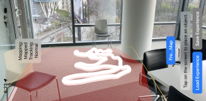
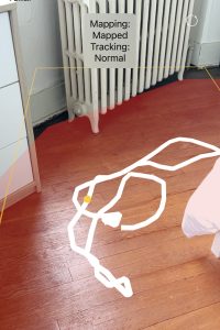
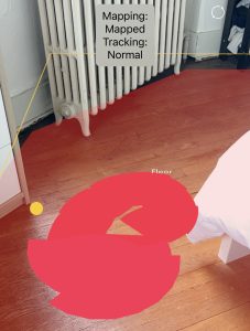
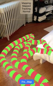
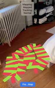
I’ve also worked on drawing a path in order to indicate its level of dirtiness. To accomplish this, I delved into experimenting with various metrics of the SCNPath and SCNLine attributes. I found that it lacked some flexibility needed to retroactively modify attributes like color based on real-time data. By changing attributes within the materials of these node objects, we are able to the color of the path. These different colors are important because they are the user indication of the varying levels of dirtiness. I can easily change the different colors of the path but doing so in a patched-way (changing line segments, drawing different lines of different colors) has been more challenging than I expected.

As shown below, I’ve been able to edit the code such that it colors different segments and can capture the segmented floor, unfortunately, there seems to be some gapping betweent he segments when turning. This is demonstrated in the images below, but the effect is still present which serves our use case. I’m going to look further into how I can mediate those gaps going forward, but the positive side is that the coloring does not seem to affect latency.

In addition to path coloring, I worked closely with Erin and Harshul on hardware integration, designing our final mount for the vacuum and actually putting the pieces together. We worked a lot in TechSpark this week and have needed each of our subsystem pieces to make progress since we are in the refinements/mounting/integration stages of our process. I fixed some bugs with reference to the freezing plane logic, and also refined the UI to actually reflect the work that we are doing rather than what was part of our initial prototype.
Next Week’s Tasks, Schedule & Challenges
