Team Status Report 4/27

This week was doing tests on our breadboard version that we presented demo videos of in our presentation. We did a bunch of tests to verify that the communication between the ESP and phone worked as well as sending messages either from the phone or from cellular itself. We expected the results to be no more than 15 seconds and all the tests passed. Regarding other tests like battery life and RFID/mic, we weren’t able to do due to the PCB not working yet and and finishing up RFID and the mic.

Anika debugged the PCB this week to figure out what was wrong and if this was an issue that can be solved or if the PCB won’t be able to work in time.  The voltage regulators were not working when we powered the board and the lithium ion battery would die every time we plugged it into the board. Because all the components worked when put tested on the breadboard, it was deemed be an issue with the board itself. At this time, because we are so close o the demo we can’t redo our PCB and need to focus on finishing implementing everything on the breadboard, which we have begun this week. We seem to be able to fit all the components onto a very small breadboard, and we will use this to represent our pendant. We also found a new battery component we can use instead of the lithium ion battery that was much smaller than the previous one.

Anika’s Status Report 4/27

This week I prepped for my final presentation and worked on debugging the PCB. We ran into a few issues with the PCB. The first one being that the 5V and 3V regulator did not work on the PCB. When We soldered a new PCB with just the voltage regulaors and no loads, the 5V regulator ended up working but the 3V3 regulator still didn’t work as it outputted the same voltage it got in. I did some tests including powering it with a different battery source  (another esp) but that didn’t work either. Another issue was that everytime i fully charged the lithium ion battery and plugged it into the PCB the battery drained almost immediately. This meant that either something was wrong with the battery or the board itself.  When I recharged the battery and plugged it directly into a breadboard instead the battery was fine which meant it was a board issue. Furthermore when i soldered wires to the the 3V3 regulator and connected it with the battery, it was able to regulate the voltage down to 3.3. Because of these issues with the PCB and with the demo being next Friday, we moved to put all our components on a small breadboard, instead. While this isn’t ideal, we want to prioritize getting everything to work. Next week we are finishing up the breadboard and trying to get RFID and the mic working by Friday.


Anika’s Status Report 4/20

This week I assembled our PCB and worked on our final presentation while recording demo videos to show the class. I’ve attached a pic of our assembled PCB below. We did run into some issues with the battery the way it needed to be plugged in but we were able to manually fix our battery connection with some header pins. We also ended up connecting our battery adapter and extra powerjack to an extra PCB we had so we can use that as a seperate charging circuit so it didn’t power our PCB while simultaneously charging. Right now we are running into some issues with our voltage regulators as our VIN is not being regulated to 5V like it should be so I need to test if the regulator works or not with some of the extra parts we have. As I’ve designed , implemented and debugged our project, tools that were necessary were definitely an understanding of the data sheets, and a lot of experimentation with libraries for the companion app.  I had to get good at understanding other code from libraries I was using in order to apply functions for my own purposes. Next week I hope to debug this voltage regulation issue.


Anika’s Status Report 4/6

This week I spent a lot of time improving certain parts the interface of the app as well as implementing the ability to actually send text messages to the inputted emergency contacts when a button is pressed and the ESP 32 sends an alert to the companion app. I also spent time creating an “alert dialog” that upon recieving a “alert!” from the esp, prompts a popup on the app asking the user to confirm or cancel the alert. If confirmed the text will be sent, and if not it gets disregarded. Additionally I began working on the geofencing interface. Thus far I have created a preference page where the user can input their home address as their reference point (using google API’s to auto-predict the address as they type) . Once they input their home address and the latitude and longitude coordinates get stored. I also have to add a button for the user to input their desired geofence radius. After this the next step is to repeatedly get the current lat and long coords and then use compute the Haversine Distance to see if we have exceeded our geofence range -> to then alert the companion app.

To verify this has been working we have been testing sending an alert with a button on the breadboard connected to the ESP.  We test when the bluetooth is disconnected whether the message has been sent via the cellular chip and if it is connected does the companion app receive the message. We also have been inputting different number of emergency contacts to see when sending a message it goes to all users. I have also repeatedly sent messages to see if my alert dialog box works (not just once and that it keeps working no matter if i cancel or confirm). There are still currently some timing issues that I am looking to fix.

I have attached a Demo with my progress below: April 6th Status Report Demo

Team Status Report 3/30

This week we have divided up work in order to present working parts for the interim demo.

Anika: establishing a connection between the companion app and the esp in order to send contact information to the esp.

Olivia:  getting the esp to send information to the cellular module

Bradley: getting the RFID working.

We’ve successfully established the first 2 parts and by the interim demo we hope to show everything connected on the breadboard to show our progress. With the progress we have so far I think we are getting back on track with our timeline.

Demo video for ESP and Companion App connection


Anika Status Report 3/30

This week I have been working on creating a bluetooth connection between our companion app and the ESP to present during our interim demo.  I’ve been working on the companion app side via flutter and I have been able to successfully establish a connection with the ESP. The next step we wanted to accomplish was to write information to the ESP about certain contacts we want to send messages to etc. To do this I created a dropdown menu allowing the user to create 3 emergency contacts. When they select “enter contact _x” they are prompted to input a phone number and “submit” upon submitting, this information gets utf8 encoded and sent to the esp in a message saying update preferences SOSx [phone number].  This message is then able to be broken down by the esp. I tested the bluetooth connection and data transmission to the esp 32 and it works successfully. I have attached a demo video showing the process. I will continue working on the PCB next week and try to get to some geofencing.

Demo Video


Anika’s Status Report for 3/23

This week I continued working on the schematic and redesigning parts of our PCB. We had a meeting with Tamal on Friday to discuss our current schematic, and Olivia and I met today to make changes accordingly discuss what parts we need to return and now buy based on our conversation with him. I initially had most of the pieces on the schematic as components to solder on, but looking at the pieces and datasheets these pieces were already on a daughter board board, so all we need to include on the actual PCB are header pins that we can mechanically place the boards into. We also upon discussion got a new digital microphone as opposed to the analog one we previously had. In addition I added decoupling capacitors to all the components on the board and modified the schematic to correctly use the voltage regulators. I replaced the voltage regulator I had for the motor from linear to switching as to not waste power. I also added header pins to connect our external 11V battery. We are stepping it down to 5V using another linear regulator and connecting that to the battery pin of our miniESP. We also are planning to return our cell module and antenna and we are ordering a new cellular dev kit instead. this already comes with a built in PCB so we discussing how we want to deal with this. (glue it onto our existing PCB and then connect physical wires from the header pins of our PCB to the cell PCB to power and transmit information? )We need to figure that out.  We also are unsure of how to connect the recharge pin of our battery. I hope to have this schematic done by tomorrow so we can send it again for feedback. I have attached the “unfinished” changes below:

Pendant PCB w_o Cellular 2 Copy

Anika’s Status Report for 3/16

This week I spent a lot of time working on the PCB schematic. We were a little behind in our timeline, so we met up multiple times this week to get all of our components sorted out and figure out exactly if our pieces were compatible with each other, and how what pins they’ll connect to on each respective component. I have been working on the PCB schematic using Fusion 360. When scanning the products in our parts list. A lot of them did not have part files included, so I have spent time creating part files myself so we can include them in our schematic and also in later to be put on the PCB itself.

Now that the PCB schematic will be finished. i plan to finish designing the PCB and have it ready to ship by the end of next week.


I have attached a pic of our schematic below:

Team Status Report for 3/9

The most significant risk to our project’s success remains consistent with our previous reports. Additionally, the complexity and depth of our project, with its many moving parts, present a substantial challenge. In order to successfully navigate this it will require a high level of dedication and effort from the team to bring our invention to life. One of the biggest issues holding us back thus far was not having all our parts figured out. While creating the design report we were able to finalize our parts list and get them ordered. We are still in budget with these changes. Now with this done, we can start to work on our PCB design to get that finished and ordered as well while we work on the parts individually in the meantime.

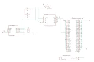
After thoroughly reviewing our materials, we have implemented some changes to the system’s overall design. The block diagram was modified after feedback from the design review in order to make our flow more understandable and have a clear logical flow on how different parts of the product come into play with each other.

Liv was also able to write the bluetooth code for communication between the ESP32 and mobile app which works for communication in both direction. We have also created a github to consolidate all our work into one location.  Our next topic we need to discuss as a team is how data gets serialized between the phone and pendant (in both directions)

The schedule in the design report is still current.

A was written by Anika, Part B by Olivia, and part C by Bradley

Part A: In regards to global factors our product is meant to be worn by any one anywhere. Outside of the Pittsburgh area what we do need to do is make sure that our product/code does not violate any sort of privacy laws anywhere else. the device is also intended to be user friendly. While there may be many moving parts we hope to mitigate this by have a very clear and concise tutorial/page on how to get started with the device. We also as we finalize tour design will hope to get feedback on our instructions as to make it as clear as possible.

Part B: In regard to cultural factors, these have not changed very much. If going into real product stages of this project and we were to develop a mass-produced item, we would need to review different religious, cultural and overall style factors to ensure that our pendant and ring could be worn by everyone. To ensure all races, genders, religions and more not only want to but are able to wear our devices, we must take into concern many factors, with current fashion ideals as well as rules with clothing due to peoples’s personal beliefs all while also maintaining discretion. While not in the process yet, this will have huge considerations during final outer design is underway.

Part C: Our device is inherently environmentally friendly, with the parts being recyclable. Also, our device uses a rechargeable battery instead of a non rechargeable, reducing waste. Ideally In terms of living organisms, our device is not related to them, as it is a personal safety device.  To make our device even more environmentally friendly, we could use recycled metals for the jewelry pieces.


Anika’s Status Report for 3/9

The week before spring break I spent a lot of time working on our Design Report and in doing so now have a better understanding of how to articulate our project and our goals to our audience as well as explain certain decisions we made throughout our design process. I also spent a lot of time based on feedback from the design review creating a concise block diagram to very clearly visually explain how each sub-component of the overall product works together and the flow of alerting SOS. Progress on the companion app remains the same as I am still looking into how to save information (from our trigger settings) and pass it back through pages for the companion app so we can use that information and pass it to our actual jewelry device, as well as researching packages for acquiring GPS location for setting the location radius triggers. Through working on the design report we have also have a more complete list of parts so I am working on finding their part files/a way for me to put those parts into our pcb design.

In the next week I hope to have information on how to achieve the 2 companion app features and make progress on our pcb design.