Team Status Report for 4/6

The most significant risks to the project are: the new motor shield not supplying enough voltage to the motor. From here we can go in two directions: we can order a higher torque motor, or we can use a shield with a higher input voltage. If our motor is not torque-y enough, we will pursue both options because we have money to spend and we need a short execution latency because we only have 3 weeks left.

The main change to the block diagram was using a new motor shield with higher input voltage. If that shield is not enough, we will use a driver with an even higher input voltage, however, since this driver is not a shield that means will need two arduinos, one to control the actuators and the other to control the motor. This will be more difficult to integrate.

We are on schedule.

Week specific answers:

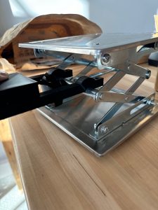
Tests we have run: stepping the motor with the driver, stepping the motor while it is mounted to the platform jack, running the motor continuously while mounted (these tests tested the structural integrity of the motor mount and the torque of the motor), and also height/angle adjustment without using actuation (i.e. we use our hands to manually change the height and the angle of the computer).

Future tests to run: torque of motor with new motor driver, running motor continuously with new motor driver, structural test of linear actuator mount. When system is fully integrated: time to complete height/angle adjustment (our goal is < 5 sec). Total weight of system (our goal is < 8 lbs). When running height adjustment, we will see if the top platform tilts, the is not good because it means the computer might fall over. We will ensure that the stand does not change height too quickly so people do not hurt themselves when sticking their fingers in between the jack arms.

Sebastian’s Status Report for 4/6

This week, I completed the mechanical assembly of the motor mount. After Mary-Rose designed the parts, I 3D printed them, multiple times due to printer failure, and drilled holes into the main mount piece so screws could secure the mount piece to the screw of the platform jack. This also involved sanding the head of the screw so the motor mount could rest on a flat surface.

I also conducted basic tests on the motor to ensure that we can drive it and that it can cause the platform jack to elevate. The motor driver we used had a limit of 10 V, but our motor needs 12-24V. So when I increased the voltage input to the driver to 24 V, a capacitor on the driver exploded. After realizing we made a purchasing error, I researched other motor drivers and settled on the Adafruit Motor Driver v2, this driver has only a max voltage input of 12 V so we will see if it is capable of meeting our goals.

I also worked on the high level algorithm for stand adjustment with Olivia. Essentially, the stand will alternately adjust heigh and angle. The condition to stop height adjustment is when your face leaves the screen. The condition to stop angle adjustment is when your face is centered.

We are on schedule and this week we hope to complete the design for the linear actuator mount, mount the actuators, 3D print the linear actuator mount, drive the main motor at a high voltage with the new driver, and integrate the whole system.

Mary Rose’s Progress Report for 3/30

This week I created the parts that will hold the motor stable while it raises the laptop stand. This required precise measurements of our current design. The final pictures of these pieces are shown below. I also re-worked the motor code for both the height motor and the linear actuators so that it will work with the new library. In addition, I got started on implementing serial communication between the laptop and the stand as this is part of our MVP for the interim demo. Using serial communication will make it easier to communicate between the software and the stand for the demo, but we will rework this using the Bluetooth code i wrote earlier for the final product. I plan on having the serial communication finished and tested by next week, as well as the code for the stepper motor and the linear actuator fully tested, and I am back on schedule.

Olivia’s Status Report for 3/30

This week I wrote the Python code that would carry out the height and angle determination of our system. The process will first need a calibration stage in which the user’s landmark data will be captured when their laptop is at the ideal height. Then, any time the user uses the device again, this data will be used as reference for determining whether to increase or decrease the height and/or angle of the laptop. The program uses an iterative process of incrementally increasing or decreasing the angle of the laptop until the vertical distance between landmarks is approximately the same as the reference distance from calibration, and then switching to adjusting the height of the laptop until the y-coordinate of the landmark at the center of the face is within threshold of the position determined at calibration. This method proved to be pretty accurate even when starting at different heights and angles.

I am also working on a method that uses position of key landmarks on the frame’s coordinate system in order to determine the height and angle adjustments that will be needed. In this method, we wouldn’t need a calibration stage for the user which may be more convenient and faster, but it seems to be less accurate in my testing.

I am currently on schedule and will continue working on this software next week and am planning to have this height and angle adjustment code integrated with the Arduino firmware in order to move the motor and linear actuators according to which adjustment is needed.

Team Status Report for 3/30

This week, we met to work on integrating the mechanical aspects of our project with our software. We worked on putting together the mount that will be attached to the stand to hold the motor and tested the motor code with the Arduino and the motor which proved to be successful. We are continuing to work on integrating the OpenCV programs and height adjustment process with the firmware for the interim demo.

Currently, the most significant risks we are facing with our project is the mechanical design and making sure that the modifications we made to the screw of the jack will allow the platform to raise smoothly and not break. Additionally, the mount we created to hold the motor will need to be sturdy and securely attached to the beams of the jack to allow the motor to be joined with the screw in order to automate the height adjustment process. To mitigate these risks, we have thought of modifications that may need to be made to our CAD designs in the case that there are issues with the stability and size of the mount.

Due to the incompatibility of the Arduino Uno Rev4 with the L293D motor driver that we had previously purchased, we made a change to the design of the system by switching the Arduino with an older version, the R3. This is a component that we already had on hand, so no additional charges are incurred.

Sebastian’s Status Report for 3/30

This week I printed the motor mount pieces needed to attach the stepper motor to the platform jack. One of the motor attachment pieces is shown below.

The 3D printing was difficult because due to the size of the prints, the print failed twice. Currently, the last set of pieces are being printed and should be ready for test tomorrow morning.

I also researched how to drive the motors using the appropriate library, power supply voltage, and ports on the motor driver. We ran into a problem where we needed to use an older motor driver library that was incompatible with our Uno R4 so we had to degrade to an Uno R3 which worked well. We achieved motor spin.

We are behind progress because this week I was supposed to work on the posture detection neural net. Instead, I will work on that next week. I delayed this progress because this is not essential for MVP. Next week my main deliverable will be training the neural net.

Sebastian’s Status Report 3/23/24

This week I modified the platform jack to allow a motor to rotate the screw. This is necessary because the motor must be stationary while it rotates the head of the screw. Before the modification, the screw head moved when you rotated it because the threaded hole it was inside of caused translation. To fix this, I sanded down part of the screw with a file so the threaded hole no causes linear motion of the screw. Below is an image of the sanded screw.

I also began setting up the neural network infrastructure for posture detection. I selected a google colab notebook that is great for general purpose neural nets and has handy graphing functions to check for overfitting.

In the next week I will begin data collection so by interim demo we will have a coarse posture detector.

Mary Rose’s Status Report for 3/23

This week I worked on designing the connection between the screw and the motor, as well as the stand and the motor. I included a sketch of the design for the block that connects the motor to the screw. This block will then be attached to the motor, allowing it to turn. The other component will attach to the bar of the platform jack to stabilize the motor while it turns the screw. My sketch for the block, and my inspiration for the motor stabilizer are shown below. The second picture is from:  https://www.thingiverse.com/thing:6161381/comments

Because of the need to create these new components, I am running a little behind in testing the code for the motors. However, I let my teammates know, and they are prepared to help if they need to.

Next week, my goal is to have these designs ready to print, and finish testing the motor code.

Olivia’s Status Report for 3/23

This week I continued working on our automatic height and angle adjustment software. After discussing with the team, we decided to do a multiple iterations of height and angle adjustment to incrementally reach the correct position rather than calculate the exact height and angle needed for adjustment. The method I am considering is to use both the vertical distance between landmarks and the y-coordinate of the facial landmark in the middle of the user’s face to determine whether the screen is positioned at the correct height and angle. Using these two measurements, we can switch between incrementing height or angle by an interval and checking these measurements until we reach an acceptable threshold of vertical landmark distance and position of the face on the screen.

I also worked on creating the GUI for our system and added the front page with buttons to choose between opening a window to use the adjustment functionality or to view the posture tracking data. When a user clicks the adjustment button, the calibration and height determination program will run.

I am currently on schedule and am aiming to finish the iterative adjustment cycle and have it coded and tested by next week.

Team Status Report 3/23

  • Right now, our largest risk is rotating the screw of for the platform jack. Because the screw head does not remain completely still while the stand is being raised, we are worried about how we are going to keep the motor stable. However, we are managing this risk by creating new components to attach to the stand in order to keep the motor in place. We have multiple design ideas in case one fails.
  • The changes made to our design are the addition of new components to keep the screw in place, a block, as well as another attachment to keep stable and connected to the bar.
  • We are still using our current schedule. As we had some slack time built in, we should be able to recover from adding these new components.