Sebastian’s Status Report for 4/27

This week I researched and sourced new components for the stand. I measured the original lead screw dimensions of the stand so I could order a copy without a knob for use in the stand. I also sourced the right motor coupler to use so we can attach our motor directly to the new lead screw. This made much a much simpler and more effective design as shown in the image below.

I also started testing the new 5:1 motor with a gearbox and thankfully it has enough torque (as calculated) to fully lift the computer up and down the full range of motion. I did a series of up/down tests with the laptop on the computer stand to ensure that the motor had enough torque and endurance to meet the user’s demands in a worst case scenario. I did 3 up/down repeated tests. I also had to design and 3D print a custom motor coupler to perform the tests because the metal motor coupler had not arrived. As a result of the tests, we have concluded that the motor torque is sufficient.

Mary Rose’s Status Report for 4/27

This week I worked on preparing to give the final presentation and increasing the precision of the communication between the computer and the Arduino. I did this by changing my packet-sending system between the Arduino and the python code. It is not fully tested yet, but it should reduce our code’s reliance on delays. I also remade the motor housing to fit the new screw and motor with the gearbox, so the stand’s design will be fully completed by tomorrow when the 3-D print finishes.

I am currently on schedule. This week I plan on refining the serial communication for the rest of our tests and the final demo, working on the poster and final writeup, and possibly implementing Bluetooth communication

Olivia’s Status Report for 4/27

This week, I added more basic functionalities to the GUI to improve usability such as buttons for going to previous pages or to the main menu, closing the adjustment or calibration process, and bug fixes for new pages. I also integrated the focus detection and stretch reminder features into the GUI so that these trackers can be activated and periodically remind users to stretch or take a break. I used multithreading for these features so that the process can be started and run outside of the main tkinter thread to periodically check the user and do computations on their landmark positions. I was able to implement notification features using tkinter’s messagebox library that will pop up on the user’s screen after a set time has passed where they have been looking at their screen or sitting for too long .

I was also able to do more tests of the adjustment algorithm using the new motor for height adjustment, and found that the intervals and delays used will need to be tweaked since the new motor’s max speed is much lower than the previous motor’s.

I am a bit behind on schedule since I am still testing the algorithm will the fully integrated system, and plan to continue working on fine tuning the process and well as refining the GUI for usability next week.

Team Status Report for 4/27

This week, we were able to integrate the new, higher torque motor with the stand and rest of the system. The new motor has sufficient torque to turn the screw of the platform jack and adjust the height of the stand. We are currently working on doing more tests with the fully integrated system as well as creating a new mount for the motor to attach the motor to the platform jack.

What are the most significant risks that could jeopardize the success of the project? How are these risks being managed? What contingency plans are ready?

Risks:

Currently, the most significant risks we are facing are the is mounting the new motor to the stand. Since the new motor is noticeably heavier than the previous one, we need to be certain that the motor mount will be able to support the weight of the motor. We also have to adjust and tune the speeds and steps we use to increase the height of the stand since there will be variations in speed when going up versus down.

Changes:

Due to the new stepper motor having different dimensions than the previous one, we had to start a new 3D print for a motor mount with these new dimensions. This cost about 60 dollars and was necessary since it is the most feasible solution to ensuring the motor is constantly in contact with the screw even when the screw’s height changes.

No changes were made to our schedule.

Unit Tests and Overall System Tests:

Unit tests we have conducted consist of testing the functionality of the linear actuator subsystem, motor control, and height and angle adjustment computations. We have conducted overall system tests of a full adjustment process – both height and angle adjustment – as well as calibration. We conducted these tests over 9 trials with the screen at starting angles and height. We found that the adjustment process took an average of 33.56 seconds, and the calibration process took an average of 6.7 seconds. The height adjustment had an error margin of about 0.95 inches, and the angle adjustment had an error margin of about 2.44 degrees.

Olivia’s Status Report for 4/20

This week I added the Manual Adjustment page to the GUI which will allow users to adjust both angle and height of the stand using button clicks that send serial commands to the Arduino similar to the system used for automatic adjustment.

I also created a focus tracking program using OpenCV that tracks the direction in which a user is looking to determine whether they are looking at their screen. This program keeps track of variations of both horizontal and vertical distances between key facial landmarks to periodically check the user’s head position, and if they have been consistently looking forward at the screen for 20 minutes, not including small breaks or movements, then they will receive a notification in the GUI reminding them to take a break to prevent eye strain. I also wrote a similar, simpler program that periodically detects whether a face is detected in frame which will be used to send notifications via GUI when a user should get up to stretch after long periods of sitting in front of their screen.

I was also able to begin testing the automated adjustment process using the linear actuators on our stand and adjusting the height of the stand manually. I tested the angle adjustment by opening my laptop to several different angles, undergoing calibration, running the angle adjustment code in the integrated subsystem, and tuning the time needed between feedback checks in OpenCV/Python. I found that 250 ms is the smallest delay that can be used between checking landmark distances before the angle adjustment becomes noticeably inaccurate.

I am currently on track, and next week, I plan to integrate the focus tracking aspects to the GUI. After we are able to supply enough torque for the platform jack’s screw rotation, I will more thoroughly test the height adjustment with the automated system.

New Tools and Knowledge:

Over the course of this project, I learned how to use OpenCV and other computer vision tools such as trained models for object classification and detection. To learn about these topics, I used many online tutorials, videos, and the OpenCV documentation to learn the basics of CV programs, and I wrote a bunch of smaller test programs to test out and learn about new features and how I could use them in our project.

Mary Rose’s Status Report for 4/20

This week I worked on redesigning the stand, as well as re working some of the motor code.

First, for the stand, I designed the lip, the flap and the linear actuator shelves. Through some weight testing on the shelves, I determined that two seperate pieces would be much lighter, which would lessen the load on the height motor.  The first shelving unit I designed was not strong enough to hold the weight of the laptop, so I created another version that was stable enough. It will be connected to the stand via a 5/8 thick block that will be screwed into the top, with the two sides of the shelf screwed into it. I laser cut this, and made it extremely lightweight. For the lip, I decided that making this out of two wooden blocks (instead of laser cutting) was the only way to make it strong enough to support the weight of the laptop. I used pine wood because it is fairly light. And did some quick tests with the laptop to ensure that it is able to support it. I laser cut the flap as one T-shaped piece. I took some measurements to determine what the dimensions of the flap should be in order to keep contact with the linear actuators, and the lip. On the finished stand, the flap will be connected to the lip via a hinge. With these new components created, I was able to remove the metal top of the stand, which further lessened the load on the height motor.

For the motor code, I integrated the new code for the big easy driver, with the existing code for the linear actuators. I also wrote a simple turn-off function that will revert the stand to its base height and angle. I started implementing the rest of the FSM as well, meaning that the Arduino will no longer need to be reset each time the app is restarted. However, this code requires further testing.

I also did some research about gearboxes for the Nema 17, so that we would not need to switch to a Nema 23 motor, which would have required us to get a new driver and power source, which would have meant completely reworking the code.

While working on the project, I needed to create new components out of wood in order to preserve our budget and keep the top of the stand light. This meant learning how to use SolidWorks to create dxf files, and learning how to use the laser cutters in TechSpark. I was able to learn how to do this by watching videos online, and reading some articles about designing shelves. I also learned more about writing code for the Arduino, including using new libraries (AF_motor.h,   ArduinoBLE.h, AFMotor.h, and Stepper.h, and AccelStepper.h). I was able to find tutorials online about how to do this. Furthermore, I learned how to implement Bluetooth communication between a mac and an Arduino. To do this I found some articles online, and also watched some videos. 

Next week, I plan to have the stand design completely finished, meaning that all the top components are connected, and are the correct measurements. In addition, I plan to have the code for the motor and the linear actuators fully integrated and tested so that the stand moves as intended when given the correct serial commands.

I am a little behind schedule, but I should be able to have the hardware complete by the final demo. If needed, I will not implement the Bluetooth communication between the Arduino and the computer, as this is not necessary to achieve MVP.

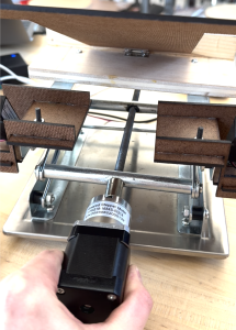
The new components for the stand:

Sebastian’s Status Report for 4/20

Over the past two weeks my work has been centered on the mechanical structure of the computer stand and testing of the stepper motor. I designed and built a structure on top of the platform jack that allows the linear actuators to change the pitch of the computer. This involved machining, and screw hole placement.

I also performed testing on the stepper motor, testing the motor at a variety of different input voltages and speeds to determine if it has sufficient torque to lift the computer (it did not).

Before this motor testing, I also researched a constant current (chopper) driver for the motor because we realized that we were using the incorrect type of motor driver. After finding a suitable driver with the right input voltage range and pin connections to our arduino, testing was possible.

Since the motor still did not have enough torque after testing, I researched gearboxes that would make the NEMA 17 have enough torque. We found a gearbox with a 5:1 ratio and a torque of 3 Nm. I calculated that we require a torque of 4.4 Nm to lift the computer but this is the worst case when the stand is in a state that is rarely exercised (all the way down).

One of the new skills I learned was to calculate the torque required to rotate a power screw (a type of screw in a platform jack). This involved straightforward physics and allowed me to better judge what kind of motor gearbox we needed. I learned this skill from a video. I also learned how to measure the main characteristics of a threaded rod so I could easily replace it with another from McMaster. I used the McMaster guidance to learnt this.

Team Status Report for 4/20

Our most significant risk is generating enough torque to lift the stand. We are currently managing this risk by purchasing a new motor that has almost 7 times the amount of torque than the one we have now. Furthermore, we have developed some ways of lightening the top of the stand. If this does not work, we will buy a motor with higher torque by the end of next week. We can also start the stand at a higher position that the motor is able to lift.

We did not make any significant changes to the design of the system other than purchasing a new motor. We also decided to include a shelf to hold the linear actuators, although this change will not incur major costs or threaten our existing schedule. This was necessary so that the laptop will start at a lower angle.


Mary Rose’s Status Report for 4/6

This week I finished the serial communication between the laptop and the Arduino. While there are still some minor syncing issues with the current implementation, it is reliable enough to achieve MVP. In addition, I rewrote the code for the height and angle motors so that it will be compatible with the new motor driver. This includes a function that will allow the two linear actuators to move at the same time.

As of right now, I am a little behind schedule. Because of issues with the motor driver not providing the stepper motor with enough power, I was not able to get the hardware completely integrated, which would have allowed me to move on to integrating the Bluetooth setup. This week, I plan on finishing the hardware integration (with serial communication) and creating the top for the stand (with slots for the linear actuators) in Solidworks.

Olivia’s Status Report for 4/6

This week I continued working on the GUI and added additional pages and features. I added a new page that allows a user to choose whether to calibrate their stand for the first time or to adjust the stand based on prior calibration data. This way, users can skip the calibration after they’ve gone through the process once. I was able to integrate the height and angle adjustment program with the Arduino via serial connection, and we are able to automate the motor and linear actuator movement.

I have done some testing with the height and angle adjustment to make sure that the algorithm we use is able to determine the correct height and angle for a user when starting from different heights and angles. I will continue testing this when we integrate the software with the stand in order to tune and make some adjustments to the time between feedback checks and speed at which we turn the motors in order to reach the ideal height and angle within our desired time limit.

I am currently on schedule. Next week I plan to add more pages to the GUI to display posture tracking data as well as implement eye tracking to the software in order to send users notifications when they have been focusing on their screen for long periods of time.