Sebastian’s Status Report for 4/27

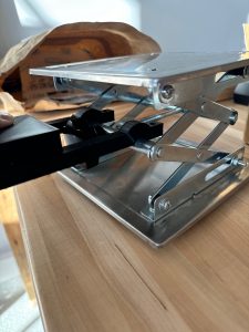
This week I researched and sourced new components for the stand. I measured the original lead screw dimensions of the stand so I could order a copy without a knob for use in the stand. I also sourced the right motor coupler to use so we can attach our motor directly to the new lead screw. This made much a much simpler and more effective design as shown in the image below.

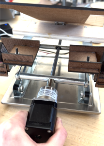
I also started testing the new 5:1 motor with a gearbox and thankfully it has enough torque (as calculated) to fully lift the computer up and down the full range of motion. I did a series of up/down tests with the laptop on the computer stand to ensure that the motor had enough torque and endurance to meet the user’s demands in a worst case scenario. I did 3 up/down repeated tests. I also had to design and 3D print a custom motor coupler to perform the tests because the metal motor coupler had not arrived. As a result of the tests, we have concluded that the motor torque is sufficient.

Sebastian’s Status Report for 4/20

Over the past two weeks my work has been centered on the mechanical structure of the computer stand and testing of the stepper motor. I designed and built a structure on top of the platform jack that allows the linear actuators to change the pitch of the computer. This involved machining, and screw hole placement.

I also performed testing on the stepper motor, testing the motor at a variety of different input voltages and speeds to determine if it has sufficient torque to lift the computer (it did not).

Before this motor testing, I also researched a constant current (chopper) driver for the motor because we realized that we were using the incorrect type of motor driver. After finding a suitable driver with the right input voltage range and pin connections to our arduino, testing was possible.

Since the motor still did not have enough torque after testing, I researched gearboxes that would make the NEMA 17 have enough torque. We found a gearbox with a 5:1 ratio and a torque of 3 Nm. I calculated that we require a torque of 4.4 Nm to lift the computer but this is the worst case when the stand is in a state that is rarely exercised (all the way down).

One of the new skills I learned was to calculate the torque required to rotate a power screw (a type of screw in a platform jack). This involved straightforward physics and allowed me to better judge what kind of motor gearbox we needed. I learned this skill from a video. I also learned how to measure the main characteristics of a threaded rod so I could easily replace it with another from McMaster. I used the McMaster guidance to learnt this.

Sebastian’s Status Report for 4/6

This week, I completed the mechanical assembly of the motor mount. After Mary-Rose designed the parts, I 3D printed them, multiple times due to printer failure, and drilled holes into the main mount piece so screws could secure the mount piece to the screw of the platform jack. This also involved sanding the head of the screw so the motor mount could rest on a flat surface.

I also conducted basic tests on the motor to ensure that we can drive it and that it can cause the platform jack to elevate. The motor driver we used had a limit of 10 V, but our motor needs 12-24V. So when I increased the voltage input to the driver to 24 V, a capacitor on the driver exploded. After realizing we made a purchasing error, I researched other motor drivers and settled on the Adafruit Motor Driver v2, this driver has only a max voltage input of 12 V so we will see if it is capable of meeting our goals.

I also worked on the high level algorithm for stand adjustment with Olivia. Essentially, the stand will alternately adjust heigh and angle. The condition to stop height adjustment is when your face leaves the screen. The condition to stop angle adjustment is when your face is centered.

We are on schedule and this week we hope to complete the design for the linear actuator mount, mount the actuators, 3D print the linear actuator mount, drive the main motor at a high voltage with the new driver, and integrate the whole system.

Sebastian’s Status Report for 3/30

This week I printed the motor mount pieces needed to attach the stepper motor to the platform jack. One of the motor attachment pieces is shown below.

The 3D printing was difficult because due to the size of the prints, the print failed twice. Currently, the last set of pieces are being printed and should be ready for test tomorrow morning.

I also researched how to drive the motors using the appropriate library, power supply voltage, and ports on the motor driver. We ran into a problem where we needed to use an older motor driver library that was incompatible with our Uno R4 so we had to degrade to an Uno R3 which worked well. We achieved motor spin.

We are behind progress because this week I was supposed to work on the posture detection neural net. Instead, I will work on that next week. I delayed this progress because this is not essential for MVP. Next week my main deliverable will be training the neural net.

Sebastian’s Status Report 3/23/24

This week I modified the platform jack to allow a motor to rotate the screw. This is necessary because the motor must be stationary while it rotates the head of the screw. Before the modification, the screw head moved when you rotated it because the threaded hole it was inside of caused translation. To fix this, I sanded down part of the screw with a file so the threaded hole no causes linear motion of the screw. Below is an image of the sanded screw.

I also began setting up the neural network infrastructure for posture detection. I selected a google colab notebook that is great for general purpose neural nets and has handy graphing functions to check for overfitting.

In the next week I will begin data collection so by interim demo we will have a coarse posture detector.

Sebastian’s Status Report for 3/16/24

This week I finished the basic proof of concept for the posture detector. Using Google’s BlazeNet pose estimation model, I was able to implement some basic thresholding on a single shoulder landmark to determine when the user is slouching. The video below shows myself sitting up straight briefly so the program can take a “snapshot” of good posture, then whenever I slouch I receive a message at the terminal telling me to fix my posture. If I don’t fix it, I keep receiving messages every 2 seconds. Once I fix my posture, the messages stop.

The link to the video on google drive is here.

I simply calculated the distance between the shoulder landmark in each frame and the “reference” frame showing myself having good posture which was captured at the start of the video. Some problems with this is that it will produce many false positives. If I shift left to right then I will get notified even if my posture remains good. For this reason, next week I will begin training a neural network for posture detection. The ability of a neural network to learn a rich and complex decision boundary makes it suitable for this application. When classifying posture in a person, many types of movement of landmarks on the body do not correspond to bad posture. I hope that the neural network will be able to learn to distinguish between movement that hints at bad posture and movement that is ok. I will be using a google co-lab notebook to train a simple neural network.

Another benefit of the neural network implementation is that our team simply has to learn from posture research what good posture is, take many photos of ourselves with that good posture, and do the same for bad posture. The neural network will do the hard work of learning what the difference is.

I am on schedule.

Sebastian Weekly Status Report Week 4

This week I helped finalize the design of the stand by settling on the platform jack configuration with linear actuators that come out of the top platform. I suggested using a platform jack because it is compact and the actuation required to elevate the top platform is very simple (just requires rotating a screw in the jack). Additionally, to change the angle of the computer I suggested using linear actuators because these are the simplest way to cause the computer to rotate forwards, thereby changing the angle the screen makes with respect to the user.

I also settled on the method of performing computer stand adjustment. We will have a calibration stage where the webcam takes not of the distances between facial landmarks when the user is facing the camera, then when the user looks straight ahead, the computer stand will adjust so that it ends up in a configuration where the distances between landmarks on the user’s face are the same as they were before.

I submitted a 3D print request to techspark and it is being processed now. Also, I made an Amazon order for the linear actuators.