As of this past week the biggest risk we have identified is our development of a power distribution board. The biggest risk is that no one on our team has experience with this type of design. Hayden and Varun are working on this design and have been reading data sheets for the components we settled on for our electronic scheme. The current contingency plan is to start early and get help from people we know that have experience in the development of power distribution boards for systems. One change we’ve made this week which was not reflected in the block diagram in our Design Review presentation was that we decided that using an Arduino Uno would simplify the pcb design for the user side because we can use it to convert to USB protocols. This change does not incur any costs because we already have three Arduinos from previous classes. We spent a lot of time this week discussing what libraries and types of software we want to use with the camera. We had a slight hiccup where the software for the camera was not running for a little bit but we have resolved this issue. While we have not made an official change to the schedule just yet, we might have to add an additional week after Spring Break to finish up fabricating the rover. The CAD design is finished! See below.
Varun’s Status Update for 2/24/24
This week went by fast!
It was mostly dedicated towards the structures of the class. We presented our Design Presentation on Wednesday, so part of the first half of the week was focused on ensuring that we gave Nathan everything he need to ace the presentation, which he did! Additionally, as a team, we have started to work on the design report due soon! I spent a good chunk of time working with part orders. Though we scoped out some parts for the design presentation, I ended up spending some time trying to ensure that the parts would fit together. A mistake that I had to rectify was the dimensions of the bellows. Upon some time spent researching about how to interface silicone with tubing, I found that I may have incorrectly scouted out components, specifically those relating to the dimensions of the pipes and the bellows. Either way, I found the correct components, and finally placed our order for a lot of the electronics.

In addition, fabrication is in full swing! I’m 3D printing parts right now, just waiting for electronics to show up (hopefully soon). With electronics in tow, my goal is to have the suction cup system done by next week, and the arm finished. We’re definitely erring on the behind side of things due to shipping; I’m hoping we get the parts soon, then things should move much quicker. In the meanwhile, I’m essentially prepping for the arrival of the parts by 3D printing holder parts.
Nathan’s Status Report for 2/17/24
For the first half of this week, I managed purchase and rental requests for equipment for our project from ECE Receiving. We initially put in a request for the Intel RealSense l515, but in order to let other teams use the equipment in the interest of fairness, we ended up purchasing the Oak D Short Range camera, which arrived yesterday. Before the new camera came, I spent most of my time doing in-depth research and making an onboarding plan to start using the camera, which included finding setup instructions and finding specific tutorials and examples to start depth perception. In addition, I started research on translating our camera output (coordinates, depth) into kinematic motion and instructions to the arm. This involved preliminary research on kinematics. The second task I did while my teammates were doing CAD design was start putting together our design review presentation. I incorporated ideas and got inspiration from previous projects in determining what to include.
Once the camera came, I briefly started the onboarding process, installing packages and getting acquainted with the software. The camera has a depthai-viewer, which is a GUI interface for viewing the output of the camera, with a preinstalled neural network. The output is shown below:

Since the camera came recently and I have spent the majority of my time on the presentation, I am a little behind on playing around with the camera. To catch up to the project schedule, I believe without the task of preparing the presentation, I should be able to dedicate most of my time towards catching up.
Next week, I hope to complete the deliverables of working together with Hayden to establish the embedded software side of the kinematics. In addition, I hope to be able to output coordinates and a depth and finalize the nominal interface between the camera and the robotic arm.
Team Status Report for 2/17/24
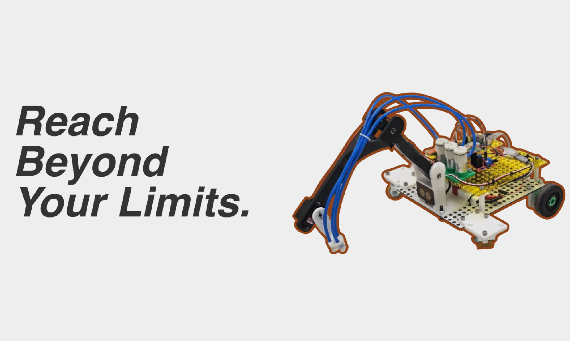
Currently, the most significant risks that could indeed jeopardize the success of the project are the actual suction mechanism reaching the desired target, and the vision of the objects. As we have successfully obtained the requisite depth camera, we will be able to begin actual work in experimenting with the hardware itself. In this way, we should actually be able to finish with the identification and location of the objects. Our concern, then, currently lays within the kinematics to reach the desired object. None of us are experienced in the kinematics side of robotics, mostly with fabrication, so we have deliberately stuck to a very simple, DOF-limited robot arm on the front of our robot that indeed should be easy to calculate with. There are many YouTube tutorials, and with the scheme that we have chosen, we already found an easy way to implement the kinematics. The devil, however, is in the details. We’re concerned at the moment about the physical implementation of these kinematics. Of course, we imagine that we’ll be able to tweak parameters and effect a change, but we’ll need to ensure that we have time to sit and tweak to ensure that things go smoothly. The block diagram of the system remains the same, but the suction design that Varun envisioned last week is a bit different from what he imagined; now we will use a DC air pump instead of a syringe to create suction. It will be a bit more expensive, but this way, we can ensure that the amount of pressure will be sufficient. Here’s a much more complete view of the draft version of HomeRover:

Part A: Varun
HomeRover, within the concept itself, is designed to meet the psychological and physical needs of those who are afflicted by a lack of mobility. Therefore, the consideration that we target is that of public health. As enumerated before, the purpose of the project is to exist such that someone who is essentially stuck in a chair can use it to grab objects around them with relative ease. As we mentioned during our proposal presentation, this idea came about due to a struggle that Hayden’s grandfather was facing. As he had recently broken his hip, he found himself stuck in a chair, with a small meter-long grabber that could not aid him to grab objects that were farther away from him that what his arm could reach. (that’s where our slogan, Reach Beyond Your Limits, comes from!) We saw an opportunity to consider his psychological and physical health, and we knew that we needed to take it.
Part B: Hayden
As far as social factors, our target audience is the elderly and our design has to be intuitive and fairly simple. We know that our design needs to be easy to use by people with minimal education on modern technology and computers, which is why our design includes a basic arrow key control system with a monitor. An additional social factor we need to consider is that older people are sometimes untrusting of new technology and might not want something like HomeRover in their home; while furthering our design we need to find a way to ensure our customers that we are not collecting data or violating privacy within their home. Lastly, when it comes to our target demographic we also know that people are more financially conservative when they are older; because of this, we have made our design as inexpensive as possible by 3D printing parts and designing our system on Raspberry Pi’s that can compute fast enough but are not super expensive.
Part C: Nathan
With regards to economic factors, the first of which we have considered is that of the system of production, specifically supply-chain availability. When deciding on Raspberry Pi’s for our main source of computing capability, one aspect we considered was whether or not there was a shortage in most major retailers. However, according to multiple websites and news sources, the shortage seems to be resolved, indicating that we would be able to produce units cheaper. As a result of this, we can reduce the overall cost of our product, appeasing our target demographic who are more financially conservative, as aforementioned. In addition, because we are 3D printing parts, there is less pressure on sourcing parts through distributors and jumping through the hoops of retailers; the agency in building and representing our design tangibly is in our control, not on the onus of third party manufacturers.
Hayden’s Status Report 2/17/24
This week I spent the majority of my time designing and finalizing the mechanical CAD for the drive train of the rover. I spent a lot of time working on creating the belt system to allow us to drive the rover with two motors. I had to do a lot of designing and redesigning to be able to fit everything on the rover and I have imported the footprints in for the electronic components we plan on putting on the rover. I am currently designing footprints for modules to hold the electronics as well as finding a premade belt that works with the pulley system our wheels have. Below is the design for the dead-shaft drive train module:

Below is the live-shaft drive train module:
I also worked on the PCB some more and found some sources that have made game controllers using an Arduino. I have started experimenting with an Arduino and analog components to bring our basic PCB design to life in a practical and fast manner. Now that the rover is almost entirely designed I need to begin looking at kinematic calculations and how to perform them internally on the Raspberry Pi.
I am slightly behind on schedule from where I should be; however, the next three weeks on the schedule are fabricating the rover. Given that the majority of our parts need to be 3D printed we will have a lot of time between prints and assembly that I can put towards getting caught up on the embedded software side involving kinematic calculations. The next 24 hours will be spent finalizing the design review presentation and making sure that our design is robust and in a good place to pitch to the class.
Varun’s Status Report for 2/17/24
This week, I focused quite a lot on designing the suction system for our robot and finalizing the robot arm. On Monday, I showed Prof Mukherjee a conceptual version of our robot arm, but upon further re-evaluation, I decided that it would be better if I designed it in a much more modular fashion. I designed modules for our torque servos and the non-torque servo (that controls the suction cups) in a way that could interface well with the previous design, so that not much change needed to be made. Here is the final design of the end effector movement Robot Arm:

The design of the arm, though it looks quite complicated, did not take nearly as much time as the conceptualization of the suction mechanism. On Monday, I showed Prof Mukherjee the mold that I had spent time designing to create the requisite suction for our project. When I tried to use some silicone resin to actually fill in the mold, I made a mess, and once it actually dried, nothing came out of the mold. I either hadn’t designed it correctly, or my process for transferring the resin was incorrect. Either way, when I came back to it on Tuesday to try and get the mold, I realized that the process of iteration for this would be unnecessary and tedious. The solution? Money. I scoped out a relatively cheap silicon bellows suction cup that would allow us to conform to the shape of the object we want to pick up, and I found one on Amazon that would work.

Pictured above are some of the pressure calculations. With this in mind, though the syringe could definitely generate enough pressure for the task at hand, I realized that we may want to use multiple suction cups. To generate enough pressure, I need a bigger syringe, and with a limited amount of real-estate on our Rover, I needed a better solution, so I found some DC air pumps that will do the job well.
Some more time was also spent on trying to figure out how to interface with the silicone. The cups I found interface with an M5 thread, and the DC pump can connect to 4 mm tubing. I found an interface between tubing and threads that fit the aforementioned numbers, and we’ll buy those on Monday!
My progress is a bit behind in my eyes, but we have a large overall goal to finish assembly by March, and I still think that is possible. From here, I will spend time to 3D print parts and ensure that we can get our hands on our physical material as soon as possible.
Varun’s Status Report for 2/10/24
This week, I focused on a few things-
- Finalizing the Pickup mechanism– As we mentioned in the presentation, we had a plan to experiment with ER fluid. ER fluid, also known as Electrorheological fluid, is a type of fluid that, when subjected to an electric field, solidifies, to the point that if it were around an object, it could theoretically pick it up. The below image demonstrates this in action.
 source
I set up a testing apparatus using a power supply, and a mixture of corn starch and silicone oil. When I tested these together, the fluid unfortunately did not solidify. I later found out that this was because I inserted leads into the fluid, and not an actual pair of plates to simulate an electric field, so there would be no way for it to work. However, upon further thought, I realized that in either case, the ER fluid gripper would not work, as the part would obstruct the electric field going through the fluid, and if the field was too strong, it may end up eating through our battery life. Luckily, I found this YouTube video which explained the process of using a syringe in order to create suction around an object using a silicone mold and a servo to actuate the syringe. The design mentioned in the video, with a miniature servo and a small syringe, could hold 300 grams. As our goal is to hold 700 grams, I conceptualized and am currently designing the suction mechanism to hold 700 grams, with a bigger servo that (according to physics first principles) should generate more upward force on the object. With this in mind, the servo itself should be of much higher torque, to physically hold the syringe in place as the suction grips the object. - Finalizing Electronics– Based on my prior experience with Combat Robotics, I began the process of designing the guts of the Rover before beginning the actual design of the structures around it. I began by doing some simple Torque Calculations, to pick the servo that would end up being at each point of the robot arm. Based on the fact that our goal is to pick up a 700 gram object at a distance of 20-30 cm away, I elected to use a 75 kg/cm servo in order to hold onto the object. Make no mistake, this is definitely overkill, but I wanted to make sure that we don’t run into an issue in the future. Based on budget constraints, I will update the power of the servo (if need be). With that in mind, I am currently finishing up the design of the Robot Arm, and we will post full pictures of the Rover design by next week (and in this post as well)!
- Learning PCB Design– Surprisingly enough, in my 3 years here, I have never needed to design a PCB, and as such did not have a great idea as to how I would go about designing one. I took a class at the RoboClub on how to design a PCB in KiCad, and below is the 3D render of how it will come out!

We’ll be populating them in the next few weeks, but that’s a separate process. Either way, this will be very useful when we are designing the on-Rover PCB.
I am on schedule, but am definitely cutting it close. I have finished a lot of the introductory knowledge that I need to have for this project, and can therefore be much closer to the timeline in the future. My next week goals are to have the kinematic scheme fully-fleshed out with Hayden and the communication protocol flushed out with Nathan, and to order parts for our project to begin work.
Nathan’s Status Report for 2/10/24
At the beginning of this week, the majority of my work went into preparing the proposal presentation slides and meeting with Hayden to finalize the presentation and offer feedback. Personally, I made the use case and problem description slides as well as created the Gantt chart and inputted the tasks we need to achieve on Asana, our technology of choice.
After the presentation and after reviewing our TA feedback, I started to research the required technologies for my end – the depth camera or a LiDAR camera. Upon discussing with the team, we decided to acquire one of each since the ECE inventory already has a LiDAR camera that we can access without cutting into our budget. I filled out a request with ECE receiving and I hope to receive the camera sometime next week so I can start playing with it. In the meantime, I am researching how to interface with the camera and any needed technologies that are required for it to function properly. Since my area of focus is mostly on software, I am also starting to research how to translate what the camera sees and the information it gathers to the kinematic motion of the arm. This is still very much a work in progress.

Currently, my progress is on schedule since I am waiting for the technologies to arrive before I can actually start digging into experimentation and research.
In the next week, I hope to be able to receive the materials and play around with them. I hope to be able to write extremely basic code for the camera and RPi and perform basic setup tasks for the two so we can establish a good basis for the coming weeks as further experimentation occurs.
Team Status Report for 2/10/24
This week, we delivered our proposal presentation. The feedback we received from the presentation was mostly about the presentation itself, so we didn’t make any change to the design from the feedback. There have been no changes to the requirements of the system; it seems that what we had for the presentation with our initial goals should be valid for the future as well. However, based on input from more experienced roboticists advising us against it for the purposes of the timescale of the semester, we made the difficult decision to abandon the intended Rocker-Bogie Suspension system (pictured below), and switched to a more common, easier to implement and calculate feedback with, four-wheel tank drive.

The biggest risk that we believe right now is the design of the software-side kinematics, in tandem with the hardware. As of current, we have on lend from the ECE department the RealSense L515; despite the initial plan to use the OAK-D SR depth camera. This weekend, before Monday, our goal is to finalize whether or not we will be able to order an OAK-D SR camera. Most likely, we should order one, but we want to make sure that the overall cost of the robot doesn’t get too high, and that we don’t spend all 600 dollars in one shot.
We have not made any changes to our schedule; we are currently on-target based on our initial Gantt chart, but we need to make sure that the design presentation does not impede the flow of work for the rest of the project.
Hayden’s Status Report for 2/10/24
This week I spent most of Sunday fine tuning the presentation and practicing for the presentation. I spent Monday morning prior to presenting reviewing our design and preparing for the presentation questions. After the presentation, I spent the rest of the week researching drive trains and CADing different designs in Autodesk Fusion 360. After researching and discussing we settled on a tank-drive system rather than a Rocker-Bogie suspension drive system. I drew both of these up in CAD just incase we want to implement the Rocker-Bogie at a later date. I also designed the modular baseplate to be able to mount our different robotic modules to the base of the robot. We decided that a peg-board type system would be best for experimentation and development.
In addition to working on the physical CAD I also touched up my PCB skills and drew up the basic PCB layout for the user controller. I found a button that could perform in the manner we wanted and that was similar to a computer key. I am currently researching methods to convert an analog high signal into USB protocol to then communicate with the Raspberry Pi on the user side.

My progress is right on schedule but I need to complete the CAD for the robot body this week. I will need to wait for Varun’s robotic arm design to properly scale parts to make sure the robot is stable. I will have the PCB completed on the user side by the end of this next week and I will have the entirety of the drive train and body of the robot mapped out. I also need to continue researching electronic speed controllers (ESCs) and other electronic components that I want to incorporate into our design.