Varun’s Status Report for 4/27/2024

This week, I presented the final presentation for the group. Additionally, I created the circuit that should be our final motor control circuit for the DC pumps on the Rover Upper Deck. This took a few tries:

For some reason (which I still cannot figure out), the motor driver on the upper deck would not output the desired nominal battery voltage on the motor output, despite the enable pin being set to high on the Raspberry Pi. To try and mitigate this, I attempted to hold the pin at 5V (necessary because the Raspberry Pi uses 3.3V signaling) and activate the pumps. They were still not receiving the voltage required when connected, which is something for which I still do not know the reason- my current speculation is max power on the board.

Eventually, I decided to implement a logic level shifter circuit to work with the motors. It is a simple power transistor circuit, attached to a logic level shifter. Testing it with raw voltage, it works, but I’m about to test to see if it works with motors (If it does, it’ll be on the final Rover.) A picture (we’re currently out of space, I’ll endeavor to fix that soon):

https://drive.google.com/file/d/1S7TOr7209yDcjg8nRn55qBP8nFoxBLN4/view?usp=drive_link

Progress is on schedule with the TechSpark demo in mind, though I will work on the ML side of things in the following days. I would like to finish the entire robot suite by next week.


Varun’s Status Report for 4/20/24

These past two weeks, I brought together the Rover’s components.

A week ago, I used the aforementioned kinematics scheme to make the arm move into the correct position when commanded. Shown here:

 (I commanded the arm to go 20 cm away)

By Sunday night, we had all the electronics made but no code to unify the parts. Initially, the thought was to use parallel processing in Python, or maybe sockets, to bring everything together, but I re-evaluated it and I was able to put everything into one while loop and have the Rover function. I created (essentially) a state machine to describe the way the Rover operated.

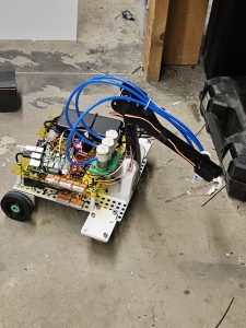
Ultimately, the Rover (draft 1):

All of the electronics were “assembled”, and it had functionality. I essentially partitioned the motion of the servos to move from Point A to B in many steps, effectively smoothing out the motion and making the arm motion more gentle. One problem it faced was that my smoothened kinematics code would operate arbitrarily, sometimes slamming the arm into the ground at full speed. I realized that I should be checking the absolute value of the difference between the arm’s current position and its last (rather than just comparing the equivalence), and the arm motion was smooth. With the state machine I wrote in Python, the Rover was able to drive from point A to B, and pick up an object once given the coordinates from the camera. Once I verified functionality, I cut out some new base plates on the iDeATe laser cutters and on Friday, we re-assembled the Rover and neatened the wiring.

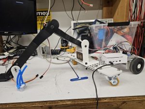
Rover (v2):

For the first time in awhile, I think that we’re on schedule. By next week, I want to make sure operation is agile and can be set up quickly, and I want to make sure that the pickup sequence is more flushed out. Right now, as I’ll cover in the final presentation, our accuracy is lower than we’d like, and I want to fix that.

I needed to re-learn python once more to make this project work. I did this by just looking up tutorials and using my pre-existing knowledge of programming in general to bring them together to make what I wanted function. I needed to learn how to create perfboard circuits, something I’ve wanted to learn for awhile now, and I was able, thanks to the motivation provided by this project. I needed to learn how to organize power electronics, and I learned that with the help of the people in Roboclub, whose help I asked quite a lot.

Varun’s Status Report for 4/6/24

This week was a landslide of new occurrences, lots of bad, few very good.

Sunday night, we discovered that our belt drive could not work with the motors that we bought with our project. As such, we switched to using casters on the front to facilitate smoother driving. With the nature of the casters, rotation is now inconsistent. What that unfortunately means, though, is that we’ll need to do feedback with the camera movement and switch to only using the DC, non-encoder motor movement. I designed the holders for the casters and we mounted them Wednesday night.

Wednesday morning, still unfortunately, we discovered that post-manufacturing, one of our servos had broken, likely from human misuse. What that meant was that I needed to rebuild some of the arm. It was at that time that the heat-set inserts in our arm began to fall apart, and the arm itself began to become undone. After verifying that our rover could drive more smoothly late Wednesday night, I verified once more that one of our servos was broken on Thursday, and debated a redesign. Unfortunately for my sleep schedule, I saw quite a lot of improvements that could be made to the initial design, and began work on redesigning the entire robot front end. By early Friday morning, the new and improved HomeRover was designed:

A couple of things that you’ll notice- a lot less moving parts were on this arm- with Roboclub’s fast-moving Bambu Printers, print times for each of these were a lot less than I expected. The camera is now at the x-center of the Rover. This is very important. Now, when we align with the object of interest, we don’t need to do more complex math and can now simplify our kinematics down even more. The arm is a lot more structurally sound. Double supported bearings on more critical joints allow for smooth movements. Now I hear you asking- Varun, is this going to add another two weeks of manufacturing time to HomeRover?
Nope! In less than 24 hours, fast printers and pre-established tolerances allowed me to fabricate the entirety of the new and improved HomeRover arm. Today, I sourced the rings that hold the wheels in place (so they won’t fall off so much). I positioned the servos such that they would not break at rest, and improved the servo at the end of the arm so that it can manipulate the final iPad more efficiently. In the end, we have a much better arm that will be more consistent. Touching on verification- I need to make sure that our arm moves consistently. While tuning our kinematics with Nathan, I need to make sure that things will not move differently than on demo day, so I will be testing the entire subsystem soon.

Great, so now we have a robot arm that is theoretically consistent, but we really need to get it to move consistently. I’m working on that too! Now that our problem has been exponentially simplified by the redesign, I was able to get my hands on a script that does that calculation for us.

With some very simple trigonometry, we have the AB and BC angles (shown above) that lead to distances that we need. Verifying our initial range, we wanted about from 10-30 cm away, and we have 11-36 cm away (according to these calculations.)

All this is very great, but I need to get the kinematics actually implemented. That’s a tomorrow issue 🙂

We are no longer nearly as behind as I thought we would, especially because the refabrication allows for that aforementioned simplification. By next week, I want to essentially have the HomeRover barebones functionality done, and I think it’s possible. By tomorrow, my goal is to be able to send the Raspberry Pi on the Rover a Y and Z coordinate (manually), and have the arm traverse correctly to that point and initiate the “pumps” (by printing out “I AM PUMPING” repeatedly into the terminal.)
Varun’s Status Report for 3/30/24

This week was a lot of physical hardware work.

Firstly, the encoder connections on the motor, which is required to drive the motors are raw 28 gauge wire. I needed to fix that in order to interface with them with the microcontroller to control the motors. As such, I soldered some spare DuPont connector wire on:

Once that was settled, the next task was to get the Raspberry Pi Pico to connect and drive the motors. Right? The Raspberry Pi Pico, right? Wrong. Turns out, with the H-bridge driver that can run the motors, one cannot use 3.3V logic to drive it. Pi Picos, being a modern microcontroller, output 3.3V logic, which indeed is not compatible to drive the motors. So, we switched to an Arduino Nano. Unfortunately, the ones I could get my hands on quickly were the cheap off-brand ones that don’t come with a pre-flashed bootloader and with a chip that indeed does not interface out of box with the Arduino software on Windows 11. After connecting an Arduino Uno to the Nano and flashing said bootloader onto the Nano, I was STILL unable to connect. The final error? Windows 11. I had to click the ‘Upload’ button in Arduino, then open up the Serial Monitor and make it a foreground task (for some reason??), and then, ONLY THEN, did the code upload. I found that neat little trick on a random reddit thread. So, the motors moved, finally. It was around this time that a fellow RoboClub member saw my usage of the 2S LiPo, and cautioned heavily against using it without a fuse as a battery-protection circuit. Luckily, we have those lying around in RoboClub, so I grabbed one and began work on the fuse box. Finally, here is what it looked like.

That pair of wires took an embarrassingly long amount of time to solder. Lastly, I designed and printed the box that would go around these wires, such that something like a random Allen Key couldn’t be accidentally dropped on the fuse and melt it unnecessarily.

With that all complete, I finally made the Rover wheels turn, safely this time. Link here:  https://drive.google.com/file/d/1zICyOJkQBSxv6ApgS1hE1o7wqdp9SjWX/view?usp=sharing

The code for the correct driving will be developed tomorrow, once we figure out an appropriate serial protocol to communicate actions across the entire control-to-Rover pipeline.

With that done, it was time to turn to how we could make the Rover Raspberry Pi receive things to drive the Nano. Hayden had already figured out a way to use his existing Nano to send signals over Serial to his laptop. We re-flashed the Raspberry Pi 4B to use a lighter OS instead of Ubuntu, so it wouldn’t be lagging all the time. Once we did that, we were able to set up communication across the CMU-DEVICE network. We realized that as it stood, the communication was much too laggy to meet our defined time, so we wanted to see if it was a hardware or comm protocol issue. To test, I set up my laptop to be the server socket side and registered it on CMU-DEVICE, after which point we tested communication from Hayden’s to my laptop. The latency instantly disappeared, so I think we’ll need a better Raspberry Pi 4B. (We ordered one with 2GB RAM but got 1GB, so we’ll need to figure that out).

All in all, a very productive week. We are much less behind, and at the rate that we are finally able to go at, we are targeting Wednesday to drive the Robot AND control the Servos. (we’re targeting driving for Monday, which is definitely possible.) By next week, I want a clean implementation of all of the electronics of the Rover drive and pickup capability. The next target after that is to finish encoder integration, after which point we can finally finish with the camera integration. I still want at least two weeks for doing full on testing and tuning, and I think on this timeline, we are still set to do that. Lots of work to be put in this week.

Varun’s Status Report for 3/23/24

This week was quite busy!

First things first, I finalized the kinematics scheme for the Rover, with the help of a Roboclub member who knows kinematics better than I do. We figured out that when the user gets to the object, the Rover should rotate til the line that the arm sits on is in line with the object to be picked up. The next step is to use the Y and Z distance from the Rover to manipulate the Robot Arm to pick up the object.

And finally, we got wheels and the arm on the Rover. This is what I wanted to be done by the end of this week, which is great. I plan to add more electronic holders to the Rover, but I really wanted to make sure that we could get the arm mounted to test it. Having the motors mounted as well, we can get the circuits done and test soon.

Progress is looking better. As you know, we are essentially pulling software tasks from the future and doing them now, so we can make up lost time. (Rover Fabrication is definitely taking awhile!) With this, I can finally start testing kinematics appropriately, and we can plan to get the tele-op portion of the Rover working by the midterm demo day. By next week, I hope to have all of the electronics + tele-op working on the Rover, and that is where mine and Hayden’s areas will cross at last.

Varun’s Status Update for 3/16/24

This week’s theme is fabrication (and ethics)! I’ll break down my week in terms of the days-

Wednesday (evening) – I spent the evening finalizing the internals of the servo box. On Tuesday morning, I realized that my original plan for assembling the servo box was inefficient, which was to use a long M3 bolt with a captive nut on the other side of the box to hold it together. I realized that if I just used a heat-set insert on the top of the larger half, I could reduce the bolt size and therefore reduce the likelihood of any shear stress snapping the bolts in half.

Thursday (evening) – Most of the day was spent on the ethics assignment, but I also found the time to print and verify the fit of the servo first stage with the servo.

Friday (whole day) – During the first part of the day, I went to TechSpark and waterjetted the parts. We were intending to waterjet on both Monday and Wednesday during class, but there were people using the waterjet during the class time; the part would take too long and eat into the next class. I began waterjetting the part on Friday morning, and much to my annoyance, there were multiple hurdles within TechSpark to get the actual board cut out; however, with an hour-and-a-half delay, I finished cutting what will serve to be the base of the Rover!

Finally, Hayden and I went back to RoboClub, where our parts were 3D printing, and ironed out some imperfections with the board. (there were some holes that for some reason hadn’t been cut out by the waterjet, and the nature of the material had created some imperfections that affected the way the board sat on the table.) The rest of the day was spent printing out the rest of the parts, and one-by-one verifying that they would fit together. Here they are! (the third stage is printing as I write this). I’ll be assembling the arm tomorrow.

We are still behind, but if we finish the arm by tomorrow (as planned), we can make up time next week (by expediting Rover manufacturing and doing integration earlier than anticipated.) By next Sunday, the physical Rover needs to be done. In my downtime, I’ll be working on verifying motor encoder functionality.

Varun’s Status Update for 3/09/24

I was able to finish the CAD for the pumps, which is quite important for the overall project, and a lot more specifically for the design review. I also worked quite a lot this week, indeed, on the design review. I worked on the implementation side of the design review, and was able to individually place screenshots of the work that I did in the design review such that I could describe each system in a more detailed fashion. As such, we ended up being right at the edge of the max quantity of pages, but we should be under the quantity limit for each individual section!

I was also, thankfully, able to work with some physical parts this week. I was able to retrieve most of the electronic guts for the Rover, which will be important as we continue to fabricate it over the next week. The most important mechanism for me to test was the suction mechanism. I wanted to make sure that with the motorized pumps, we would be able to lift our target weight. When I got the pump in the initial part delivery, I found that it could only push air out, not pull air in. After I spent awhile inspecting the inside of the pump, I figured out how I could add a 3D printed part and essentially add a suction input. A picture:

The blue plastic part above is the 3D printed part. Though this did add some suction, it wasn’t nearly enough to hold my iPad, which is our weight goal. I was able to source an original plastic heading for the DC pump that had the suction in-built, and with just two pumps, we were able to lift an iPad, our target weight! The video.

Though this is good, we are still a bit behind on fabrication. We have cut time on other things, such as with the OAK-D SR, which should keep us on track, but we’ll have to put a bit more time this week to meet our fabrication goal. I hope by next week to have the completed Rover; if not, the Robot Arm fabricated.

Varun’s Status Update for 2/24/24

This week went by fast!

It was mostly dedicated towards the structures of the class. We presented our Design Presentation on Wednesday, so part of the first half of the week was focused on ensuring that we gave Nathan everything he need to ace the presentation, which he did! Additionally, as a team, we have started to work on the design report due soon! I spent a good chunk of time working with part orders. Though we scoped out some parts for the design presentation, I ended up spending some time trying to ensure that the parts would fit together. A mistake that I had to rectify was the dimensions of the bellows. Upon some time spent researching about how to interface silicone with tubing, I found that I may have incorrectly scouted out components, specifically those relating to the dimensions of the pipes and the bellows. Either way, I found the correct components, and finally placed our order for a lot of the electronics.

In addition, fabrication is in full swing! I’m 3D printing parts right now, just waiting for electronics to show up (hopefully soon). With electronics in tow, my goal is to have the suction cup system done by next week, and the arm finished. We’re definitely erring on the behind side of things due to shipping; I’m hoping we get the parts soon, then things should move much quicker. In the meanwhile, I’m essentially prepping for the arrival of the parts by 3D printing holder parts.

Varun’s Status Report for 2/17/24

This week, I focused quite a lot on designing the suction system for our robot and finalizing the robot arm. On Monday, I showed Prof Mukherjee a conceptual version of our robot arm, but upon further re-evaluation, I decided that it would be better if I designed it in a much more modular fashion. I designed modules for our torque servos and the non-torque servo (that controls the suction cups) in a way that could interface well with the previous design, so that not much change needed to be made. Here is the final design of the end effector movement Robot Arm:
 
The design of the arm, though it looks quite complicated, did not take nearly as much time as the conceptualization of the suction mechanism. On Monday, I showed Prof Mukherjee the mold that I had spent time designing to create the requisite suction for our project. When I tried to use some silicone resin to actually fill in the mold, I made a mess, and once it actually dried, nothing came out of the mold. I either hadn’t designed it correctly, or my process for transferring the resin was incorrect. Either way, when I came back to it on Tuesday to try and get the mold, I realized that the process of iteration for this would be unnecessary and tedious. The solution? Money. I scoped out a relatively cheap silicon bellows suction cup that would allow us to conform to the shape of the object we want to pick up, and I found one on Amazon that would work.
 
Pictured above are some of the pressure calculations. With this in mind, though the syringe could definitely generate enough pressure for the task at hand, I realized that we may want to use multiple suction cups. To generate enough pressure, I need a bigger syringe, and with a limited amount of real-estate on our Rover, I needed a better solution, so I found some DC air pumps that will do the job well.
Some more time was also spent on trying to figure out how to interface with the silicone. The cups I found interface with an M5 thread, and the DC pump can connect to 4 mm tubing. I found an interface between tubing and threads that fit the aforementioned numbers, and we’ll buy those on Monday!
My progress is a bit behind in my eyes, but we have a large overall goal to finish assembly by March, and I still think that is possible. From here, I will spend time to 3D print parts and ensure that we can get our hands on our physical material as soon as possible.

Varun’s Status Report for 2/10/24

This week, I focused on a few things-

  1. Finalizing the Pickup mechanism– As we mentioned in the presentation, we had a plan to experiment with ER fluid. ER fluid, also known as Electrorheological fluid, is a type of fluid that, when subjected to an electric field, solidifies, to the point that if it were around an object, it could theoretically pick it up. The below image demonstrates this in action.
    source
    I set up a testing apparatus using a power supply, and a mixture of corn starch and silicone oil. When I tested these together, the fluid unfortunately did not solidify. I later found out that this was because I inserted leads into the fluid, and not an actual pair of plates to simulate an electric field, so there would be no way for it to work. However, upon further thought, I realized that in either case, the ER fluid gripper would not work, as the part would obstruct the electric field going through the fluid, and if the field was too strong, it may end up eating through our battery life. Luckily, I found this YouTube video which explained the process of using a syringe in order to create suction around an object using a silicone mold and a servo to actuate the syringe. The design mentioned in the video, with a miniature servo and a small syringe, could hold 300 grams. As our goal is to hold 700 grams, I conceptualized and am currently designing the suction mechanism to hold 700 grams, with a bigger servo that (according to physics first principles) should generate more upward force on the object. With this in mind, the servo itself should be of much higher torque, to physically hold the syringe in place as the suction grips the object.
  2. Finalizing Electronics– Based on my prior experience with Combat Robotics, I began the process of designing the guts of the Rover before beginning the actual design of the structures around it. I began by doing some simple Torque Calculations, to pick the servo that would end up being at each point of the robot arm. Based on the fact that our goal is to pick up a 700 gram object at a distance of 20-30 cm away, I elected to use a 75 kg/cm servo in order to hold onto the object. Make no mistake, this is definitely overkill, but I wanted to make sure that we don’t run into an issue in the future. Based on budget constraints, I will update the power of the servo (if need be). With that in mind, I am currently finishing up the design of the Robot Arm, and we will post full pictures of the Rover design by next week (and in this post as well)!
  3. Learning PCB Design– Surprisingly enough, in my 3 years here, I have never needed to design a PCB, and as such did not have a great idea as to how I would go about designing one. I took a class at the RoboClub on how to design a PCB in KiCad, and below is the 3D render of how it will come out!

    We’ll be populating them in the next few weeks, but that’s a separate process. Either way, this will be very useful when we are designing the on-Rover PCB.

I am on schedule, but am definitely cutting it close. I have finished a lot of the introductory knowledge that I need to have for this project, and can therefore be much closer to the timeline in the future. My next week goals are to have the kinematic scheme fully-fleshed out with Hayden and the communication protocol flushed out with Nathan, and to order parts for our project to begin work.