Hayden’s Status Report for 4/27/24

This week my workload was divided into three different categories: the first was finishing the final presentation and making sure our metrics for testing were presentable. I spent most of Sunday working on touching up the presentation and helping Varun prepare for presenting. The rest of the week I spent assembling the new pcb as well as the monitor setup for the user side. I also spent time working with Nathan researching how to pipeline the camera feedback effectively; we have made significant progress and I have no doubt it will be done by Wednesday. The latter part of the week has been spent drafting up our poster design and planning for the deliverables for this next week. A lot of the work we have been doing is to make sure our project is presentable this coming week.

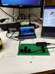
Image of the user side setup.

In order to meet our Tuesday deadline we have to finish our poster design; in order to meet our Wednesday deadline we need to get the camera feed working. I will be spending the next three days working closely with Nathan to make sure we get the camera feed transmitted as well as helping Varun wherever debugging and verification is necessary for the kinematics. No schedule changes need to be made and quite frankly we do not have the opportunity to make any.

Hayden’s Status Report for 4/20/24

These past two weeks I have focused on improving the user experience. I found a monitor and have connected it to the Raspberry Pi. Nathan and I are still trying to find a way to transmit the camera feed back to the monitor but we could just directly SSH into the rover RPi if it comes down to it. I also spent this week redoing the PCB to make it have better keys and I made it more like a controller. I also designed a user terminal that will hold the battery and the Rpi/monitor and allow the user to adjust the angle. On top of this I have spent countless hours with Varun rebuilding the rover and testing it to make sure it still works every time we redo the electronics. I also have crafted some beautiful slides for our final presentation on Monday.
Here are some photos of the new PCB design, the current setup and the CAD for the new terminal I have designed.

We are very much on track to finish things; I do not need to modify the timeline at all, I just need to focus and get the deliverables done.
In the next week I will keep helping Varun calibrate the rover as I have been doing and figure out how to get the video feedback.

As I’ve been designing my side of the project I have had to improve my physical CAD skills with Fusion 360 to be able to create a fully integrated design. I also found it necessary to learn about new libraries in Python and learn about serial and socket communication methods. I have spent a lot of time reading data sheets and library documentation to be able to get a thorough understanding of what is happening in our design and figuring out how to debug it. The learning strategy that has proved to be the most effective has been reading these documents and then trying to implement the concepts into our design and then use previous knowledge to debug.

Hayden’s Status Report 4/6/24

This week I spent four hours on Sunday debugging our communication protocol and establishing connection between the controller and the rover to allow driving to be demonstrated. After we achieved driving functionality and demonstrated I worked on rewiring and cleaning up the rover to make sure we will be able to fit everything on it. This week was heavily based on verification for me because I have completed the subsystem that I was in charge of. As far as verification I checked the latency of transmission between the two computers and found the latency was consistently less than 100ms which meets our design requirements (averaged about 15 ms, not sure if I measured properly but I count this as verified). I ended up putting a set delay/latency of 10 ms in the Python code just to make sure everything between the two systems was consistent; without this delay we had some interesting bugs.

As far as the latency of the direct wiring on the rover and in the controller I used the slowmo function of my iPhone 14 pro which has a frame rate of 240fps which allows us to detect latency to approximately 4ms. From this test I was able to confirm that the latency was below 20ms in both cases with the key press reaction being approximately 10ms (limited by the frame rate) and the rover motor reaction, which I ballparked by looking at the approximate time it started driving, to approximately 15ms. While I am not entirely convinced the measurements are the most accurate they are good enough for the design requirements we have outlined. I also scaled down the board size of the PCB and I am trying to source a Raspberry Pi 4 with greater RAM because that seems to be the bottleneck for the speed of the controller (I tried using different power sources, different WiFi connections and downloading different operating systems and the python code still was running too slow).

Given that the subsystem I was put in charge of ended up being much less involved than we initially expected I will be spending the rest of the time working on the arm kinematics with Varun and verifying the suction mechanism works as intended. We plan on verifying this system by lifting actual objects with the suction and making sure the servos and 3D printed components are strong enough to hold up to the weight of an iPad. I do not foresee any necessary schedule changes since we updated our Gantt chart and have cut time on certain tasks. I found a Raspberry Pi monitor I think will be perfect for our controller and is in our price range; I will place the order this week.

In the next week I will work with Varun to finalize arm movement and suction and begin system validation tests such as driving to a location and pressing the pickup button.

Hayden’s Status Report 3/30/24

This week I accomplished a lot; I was able to interpret the serial USB data on my laptop and convert it into inputs for python code. This is going to make the project a lot easier from here on out now that we have access to the useful data we want to transmit. Unfortunately, the Raspberry Pi we requested is too slow because it only has 1 GB of RAM so we had to demonstrate the communication laptop to laptop. On Friday, Varun and I were able to get the motors moving and we worked on the electronics for the drive train; we also 3D printed a few more parts that are necessary for our rover. I am confident that we will be able to display full driving capabilities for the interim demo on Monday which was our goal. Overall, I am in a significantly better place than I was at this time last week; I do not think I need to make any further changes to my required tasks and timeline.

In the next week I will be completing the full communication of the driving with the proper Raspberry Pis and have a prototype on the user side for entirely controlling the system. After I complete this I will be able look into monitors and hopefully assess the Raspberry Pi to make sure it has enough processing power to relay video information while keeping the latency low.

Below is a video of two laptops communicating using the test PCB.
VIDEO LINK

Here are some screenshots of the current state of the basic code.
Changes to the Arduino Code

Transmitter Side/User Side Code

Receiver/Server Side Code

Hayden’s Status Report 3/23/24

This week I received the PCB and debugged it and everything seems like it will work in our context. We do not like the buttons we chose so our final design will use a different footprint for buttons. I also figured out we need to use an Arduino Nano ESP32 rather than an Arduino Nano Every; this is because of the USB protocol and wanting to use this for the python code I will be writing on the user side. I also made the decision to write the code in Python on the user side because it will be relatively basic and has a keyboard interrupt library.

We need to simplify some of our stuff because we are about a week and a half behind as of right now and I decided that simplifying the code for sending signals to the rover is going to help us make up some time. We have also finished fabricating all the necessary parts for the drivetrain and we are currently assembling the rover and should have it complete as soon as we receive the wheels.

Below is a video of the PCB working with the serial monitor as well as a photo of the PCB. Sorry about the focus on the camera I don’t have a tripod to hold it. To see photos of the rover assembly see Varun’s post; however I also attached some of the print files.

Video of the PCB


Photo showing the USB setup of the PCB


Photo showing the print for the dead shaft mounting bracket and the live shaft gears.

This week I will be cutting out the washers, finalizing the rover construction and writing python code for the user side that will transmit from one Raspberry Pi to another. I also need to make a decision what language I will be writing the driving code in that will meet our design requirements for response time. I will order the second Raspberry Pi as well as a monitor so I can finalize the controller before the interim demo.

Hayden’s Status Report 3/16/24

This week I made a lot of progress. I spent Friday helping Varun fabricate parts for the robot arm. We should be able to complete the drive train parts in the next few days. I also finished the PCB design and will be able to order it ASAP once I confirm the parts are available on the website. I got a breadboard and tested my code from last week and it works; now that the code works the PCB was designed to work with this code. After we finish fabricating the rover in the next week we will be able to work on the kinematics; I have finished my research for the driving kinematics and I am currently looking into Wi-Fi communication between RPis so I can get that up and running after the rover is built.

Attached are some screenshots of the PCB and the code working for the controller:

This is the breadboard I used to confirm the design.

We are still behind on fabricating the rover, but once we have it created I believe it will be much easier for us to write meaningful code for the kinematics and debug it. We are on track to have a moving rover by the interim demo.

In order for things to be on track I need to purchase the drive train components by Wednesday and have all the other components 3D printed by then as well. I will also order the PCB ASAP because it might take a while to ship. I also need to confirm with other members of the group that we have purchased/acquired the RPis and the monitor to make sure we can get the controller side complete in the next two weeks.

Hayden’s Status Report 3/09/24

These past two weeks I’ve spent the majority of my time verifying the design and touching up the CAD so we will be able to hit the ground running after Spring Break with fabrication of our rover. I spent probably about 8 hours alone confirming our design and finding sources for our design proposal report. As far as progress, I have not been able to work on the physical fabrication our experimentation parts because I was ill the week prior to Spring Break and then I have been out of town. However, while working on our design report submission I confirmed the ability of our design to drive, lift items properly, and receive data from the encoder on the servos at a high enough rate to have the amount of control we would like.

Additionally, I finally had the time to write some Arduino code and I was able to get the analog button presses to translate to outputs from the Arduino. Here is the basic code I was able to write with the help of one of our design sources.

Looking at the schedule I am pretty much on task as far as design; nevertheless, I am very far behind as far as fabrication. This week Varun and I plan on using the water jet to create our bottom plate and we will be able to keep 3D printing components. Once, we order the final components of the drive train we will be able to assemble the entire rover and the only part we will have left is integration. We were very optimistic in believing that we could fabricate the entire rover before break but now that our design is set in stone I believe we will be able to get caught up in the next two weeks. Kinematics is still in the works and I need to put a lot more effort into the coding aspect of the project now that the CAD is finalized. This next week I will finish the entirety of the 3D printed drive train modules and I will finalize a PCB so I can order one and begin debugging ASAP.

Hayden’s Status Report 2/24/24

This week was way less productive than I wanted it to be. Sunday was dedicated to finishing up the CAD for the rover and finalizing our design review presentation. While I did not accomplish much in terms of completing design tasks for the rover beyond the CAD, I spent a lot of time learning how to calculate kinematics for the motion of the rover. I should be able to start working on the software system for the drive train. Since the drive train and the design are now finalized I was able to calculate the RPM we need the motor to spin to meet our target max speed of 0.5m/s. Given the fact the wheels are 2.5 inches in diameter we need to have an RPM of 150 to be at the maximum of our driving speed. I have began to relearn and mess around with Arduino code from the following sources that are inspiring the PCB design:
Source 1
Source 2
Source 3

Unfortunately I fell ill towards the end of the week and I have not been able to fabricate parts with Varun; nor have I been super productive. However, I am finally back on schedule and the time I’ve taken to learn kinematics and review Arduino programming will definitely streamline things in the future. In the next week I will finalize the PCB design and test my Arduino code with a basic breadboarded circuit. I will also help out as much as I can with fabricating the physical rover. Once again we are very proud of our CAD so here is another angle:

Hayden’s Status Report 2/17/24

This week I spent the majority of my time designing and finalizing the mechanical CAD for the drive train of the rover. I spent a lot of time working on creating the belt system to allow us to drive the rover with two motors. I had to do a lot of designing and redesigning to be able to fit everything on the rover and I have imported the footprints in for the electronic components we plan on putting on the rover. I am currently designing footprints for modules to hold the electronics as well as finding a premade belt that works with the pulley system our wheels have. Below is the design for the dead-shaft drive train module:

Below is the live-shaft drive train module:

I also worked on the PCB some more and found some sources that have made game controllers using an Arduino. I have started experimenting with an Arduino and analog components to bring our basic PCB design to life in a practical and fast manner. Now that the rover is almost entirely designed I need to begin looking at kinematic calculations and how to perform them internally on the Raspberry Pi.

I am slightly behind on schedule from where I should be; however, the next three weeks on the schedule are fabricating the rover. Given that the majority of our parts need to be 3D printed we will have a lot of time between prints and assembly that I can put towards getting caught up on the embedded software side involving kinematic calculations. The next 24 hours will be spent finalizing the design review presentation and making sure that our design is robust and in a good place to pitch to the class.

Hayden’s Status Report for 2/10/24

This week I spent most of Sunday fine tuning the presentation and practicing for the presentation. I spent Monday morning prior to presenting reviewing our design and preparing for the presentation questions. After the presentation, I spent the rest of the week researching drive trains and CADing different designs in Autodesk Fusion 360. After researching and discussing we settled on a tank-drive system rather than a Rocker-Bogie suspension drive system. I drew both of these up in CAD just incase we want to implement the Rocker-Bogie at a later date. I also designed the modular baseplate to be able to mount our different robotic modules to the base of the robot. We decided that a peg-board type system would be best for experimentation and development.

In addition to working on the physical CAD I also touched up my PCB skills and drew up the basic PCB layout for the user controller. I found a button that could perform in the manner we wanted and that was similar to a computer key. I am currently researching methods to convert an analog high signal into USB protocol to then communicate with the Raspberry Pi on the user side.

My progress is right on schedule but I need to complete the CAD for the robot body this week. I will need to wait for Varun’s robotic arm design to properly scale parts to make sure the robot is stable. I will have the PCB completed on the user side by the end of this next week and I will have the entirety of the drive train and body of the robot mapped out. I also need to continue researching electronic speed controllers (ESCs) and other electronic components that I want to incorporate into our design.