Varun’s Status Report for 4/27/2024

This week, I presented the final presentation for the group. Additionally, I created the circuit that should be our final motor control circuit for the DC pumps on the Rover Upper Deck. This took a few tries:

For some reason (which I still cannot figure out), the motor driver on the upper deck would not output the desired nominal battery voltage on the motor output, despite the enable pin being set to high on the Raspberry Pi. To try and mitigate this, I attempted to hold the pin at 5V (necessary because the Raspberry Pi uses 3.3V signaling) and activate the pumps. They were still not receiving the voltage required when connected, which is something for which I still do not know the reason- my current speculation is max power on the board.

Eventually, I decided to implement a logic level shifter circuit to work with the motors. It is a simple power transistor circuit, attached to a logic level shifter. Testing it with raw voltage, it works, but I’m about to test to see if it works with motors (If it does, it’ll be on the final Rover.) A picture (we’re currently out of space, I’ll endeavor to fix that soon):

https://drive.google.com/file/d/1S7TOr7209yDcjg8nRn55qBP8nFoxBLN4/view?usp=drive_link

Progress is on schedule with the TechSpark demo in mind, though I will work on the ML side of things in the following days. I would like to finish the entire robot suite by next week.


Nathan’s Status Report for 4/27/24

This week, I personally accomplished two main tasks. First, I edited the depth pipeline to finally be able to utilize the ColorCamera ability of the camera. Specifically, using the same mobilenet framework, I was able to make the two StereoDepth inputs come from the color camera and utilize the color camera for input into the spatial network pipeline as well as for display. The updated code can be seen here https://github.com/njzhu/HomeRover/blob/main/depthai-tutorials-practice/1-hello-world/depth_script_color.py

Additionally, a photo demonstrating this color functionality is shown here: We can see a bounding box around Hayden, demonstrating that the pipeline is able to make detections. A closer glimpse into the code can be seen here: https://drive.google.com/file/d/1MTEEsWslS3K_79CAxSCOV2DoH274E5bl/view?usp=sharing

From this photo, we can see the linking together of the pipeline, starting from the color cameras, going through stereo depth, and ending at the spatial detection output.

The second main task I accomplished was that I was able to put a live camera feed onto a locally-hosted website. To achieve this, I followed and adapted a Flask tutorial to setup the website, html pages, and routing actions. We plan on having the controller Pi access this website to display it on the display. One challenge was similar to a previous issue of multithreading and accessing variables in different files. To overcome this, I combined the code of my depth pipeline with the locking and unlocking required to update the frame to be displayed on the website. A video showing the live camera feed updating on the website can be found here: https://drive.google.com/file/d/1kDW8dthBEhdgHHi2DJDfmURngqmv2ULZ/view?usp=sharing

After this week, I believe my progress is on schedule because a point of worry from last week was the ability to broadcast the video and live camera feed for the user, but a major component of that functionality was figured out today, which is good.

In this coming week, I hope to be able to fully finalize the rover in a culmination of all of our combined effort over the semester. In addition, I hope to, together with the team, finalize all the requisite documents as well.

Hayden’s Status Report for 4/27/24

This week my workload was divided into three different categories: the first was finishing the final presentation and making sure our metrics for testing were presentable. I spent most of Sunday working on touching up the presentation and helping Varun prepare for presenting. The rest of the week I spent assembling the new pcb as well as the monitor setup for the user side. I also spent time working with Nathan researching how to pipeline the camera feedback effectively; we have made significant progress and I have no doubt it will be done by Wednesday. The latter part of the week has been spent drafting up our poster design and planning for the deliverables for this next week. A lot of the work we have been doing is to make sure our project is presentable this coming week.

Image of the user side setup.

In order to meet our Tuesday deadline we have to finish our poster design; in order to meet our Wednesday deadline we need to get the camera feed working. I will be spending the next three days working closely with Nathan to make sure we get the camera feed transmitted as well as helping Varun wherever debugging and verification is necessary for the kinematics. No schedule changes need to be made and quite frankly we do not have the opportunity to make any.

Nathan’s Status Report for 4/20/24

These past two weeks, I did a lot of collaborative group work in integrating all the requisite parts required for a full implementation of the rover. For instance, one thing I did was help solder the third pump for our suction arm, as seen here. I also contributed to the group’s effort in the foray of investigating multiprocessing in Python.

In addition, I also helped setup a testing suite for analyzing the coordinates and bounding box dimensions in our object detection pipeline, as well as analyzing what these different variables refer to. The testing suite can be seen below. I took the various detection.y, ymin, ymax, and other similar coordinates and measured spatially with a ruler to determine how the camera is calibrated.

I also investigated potentially abandoning a neural network altogether and using openCV thresholding, contouring, and rectangle-creating functions to use the depth color map to extract an object that is close enough. However, this idea fell short because as we would get closer to an object, the floor would also be lower than our desired object’s z-distance threshold, meaning the heatmap would reflect that the floor is just as close as the object. If I were to try and manually create a bounding box, it would also include the floor; there would be no way to differentiate. In addition, as the video frame displays, I saw some blips on the heatmap that showed closeness that wasn’t part of the object. These small blips could potentially cause issues if I were to threshold the frame since they wouldn’t be greyed out.

My progress is flip-flopping between mainly on schedule and a teeny bit behind, mainly because problems arise when performing integration tests that did not appear when doing unit tests, such as the lower accuracy resulting from the object detection pipeline. Since we budgeted this time, I would consider progress to be on schedule.

The main deliverable I hope to complete in the next week is to tweak and adjust the object detection pipeline so when we perform validation tests, we meet our desired accuracy threshold as described in our use case requirements. Additionally, I hope to be able to work with Hayden to successfully transmit the camera feed back to the monitor.

Throughout the semester, the acquisition of new knowledge was a particularly salient undertaking due to the fact that I had to learn and get used to the depthai module, features, and programming paradigm. To be able to accomplish these tasks and successfully utilize the module, I found it necessary to be able to learn quickly, which I tackled through sifting through the wide variety of examples created by depthai’s Luxonis. I utilized their depthai-examples repository, which had example programs for every feature of the camera, from spatial detection, object tracking, and depth. Being able to see example programs really allowed me to learn and quickly get acclimated to the module, and in addition, when searching the internet to help solve my error messages, I found forum posts and discussions that really helped my debugging process, which was especially helpful because the camera is so new and constantly undergoing changes when compared to different versions and models.

Team Status Report for 4/20/24

For the past two weeks, the main thing we as a team have been working on revolves around integration and connecting together all our separate subsystems.  When connecting our object detection/depth map code that instructs the motors to turn and move a specific direction, we ran into difficulty parallelizing the two processes, either using Python’s multiprocessing and socket modules. The two control loops were blocking each other and preventing us from progressing in either program, but as stated in Varun’s status report, the end program is an overarching one acting as a state machine. After fully assembling the rover and running integration tests that involve the full pipeline of navigation -> detection -> pickup, the most significant risk lies on the detection side. Earlier in the week, we were running into an issue with the coordinates that the object detection pipeline was giving for the bounding box it created in that the y-coordinate it outputted wasn’t necessarily the top of of the object, but the center relative to some part of the camera, causing our suction to undershoot because of inaccurate kinematics. After investigating the various dimensions and y-values that exist in the code and comparing them to our hand measurements, we found that the detection.y value it spit out did reflect the top of the object, but regarding its magnitude, it reflected the distance from the bottom of the camera. To mitigate and manage this risk, as well as improve our kinematics in the process, we plan on finetuning a potential hard offset to all y values to ensure that we hit the top of the object as well as tuning with adding a variable offset based on the bounding box dimensions. We have started doing this, but plan on performing a lot more trials next week. Another risk involves the accuracy of the object detection, which meets below our standards as defined in the design and use case requirements. A potential cause for this issue is that since mobilenetSSD has a small label database, there’s a chance it doesn’t encompass all the objects we want to pickup, but since we don’t necessarily need identification, just detection, a potential risk mitigation strategy is to lower the confidence threshold of the detection pipeline to hopefully improve on detection accuracy.

One change that was made to the design of the system was adding a second layer to our rover to house our electronics due to space constraints. The change does not incur major costs since the material and machinery were both provided by Roboclub. This is a quick, lasting fix, with not further costs needing mitigation going forward.

As stated in our individual status reports, we are fairly on track, with no major changes to the schedule needed.

A full run-through of our system can be found here, courtesy of Varun: https://drive.google.com/file/d/1vRQWD-5tSb0Tbd89OrpUtsAEdGx-FeZF/view?usp=sharing

Varun’s Status Report for 4/20/24

These past two weeks, I brought together the Rover’s components.

A week ago, I used the aforementioned kinematics scheme to make the arm move into the correct position when commanded. Shown here:

 (I commanded the arm to go 20 cm away)

By Sunday night, we had all the electronics made but no code to unify the parts. Initially, the thought was to use parallel processing in Python, or maybe sockets, to bring everything together, but I re-evaluated it and I was able to put everything into one while loop and have the Rover function. I created (essentially) a state machine to describe the way the Rover operated.

Ultimately, the Rover (draft 1):

All of the electronics were “assembled”, and it had functionality. I essentially partitioned the motion of the servos to move from Point A to B in many steps, effectively smoothing out the motion and making the arm motion more gentle. One problem it faced was that my smoothened kinematics code would operate arbitrarily, sometimes slamming the arm into the ground at full speed. I realized that I should be checking the absolute value of the difference between the arm’s current position and its last (rather than just comparing the equivalence), and the arm motion was smooth. With the state machine I wrote in Python, the Rover was able to drive from point A to B, and pick up an object once given the coordinates from the camera. Once I verified functionality, I cut out some new base plates on the iDeATe laser cutters and on Friday, we re-assembled the Rover and neatened the wiring.

Rover (v2):

For the first time in awhile, I think that we’re on schedule. By next week, I want to make sure operation is agile and can be set up quickly, and I want to make sure that the pickup sequence is more flushed out. Right now, as I’ll cover in the final presentation, our accuracy is lower than we’d like, and I want to fix that.

I needed to re-learn python once more to make this project work. I did this by just looking up tutorials and using my pre-existing knowledge of programming in general to bring them together to make what I wanted function. I needed to learn how to create perfboard circuits, something I’ve wanted to learn for awhile now, and I was able, thanks to the motivation provided by this project. I needed to learn how to organize power electronics, and I learned that with the help of the people in Roboclub, whose help I asked quite a lot.

Hayden’s Status Report for 4/20/24

These past two weeks I have focused on improving the user experience. I found a monitor and have connected it to the Raspberry Pi. Nathan and I are still trying to find a way to transmit the camera feed back to the monitor but we could just directly SSH into the rover RPi if it comes down to it. I also spent this week redoing the PCB to make it have better keys and I made it more like a controller. I also designed a user terminal that will hold the battery and the Rpi/monitor and allow the user to adjust the angle. On top of this I have spent countless hours with Varun rebuilding the rover and testing it to make sure it still works every time we redo the electronics. I also have crafted some beautiful slides for our final presentation on Monday.
Here are some photos of the new PCB design, the current setup and the CAD for the new terminal I have designed.

We are very much on track to finish things; I do not need to modify the timeline at all, I just need to focus and get the deliverables done.
In the next week I will keep helping Varun calibrate the rover as I have been doing and figure out how to get the video feedback.

As I’ve been designing my side of the project I have had to improve my physical CAD skills with Fusion 360 to be able to create a fully integrated design. I also found it necessary to learn about new libraries in Python and learn about serial and socket communication methods. I have spent a lot of time reading data sheets and library documentation to be able to get a thorough understanding of what is happening in our design and figuring out how to debug it. The learning strategy that has proved to be the most effective has been reading these documents and then trying to implement the concepts into our design and then use previous knowledge to debug.

Nathan’s Status Report for 4/6/24

This week on the project, I helped integrate the Raspberry Pi program that successfully receives button presses serially from the controller and simultaneously transmits the results serially to the Arduino Nano that controls the turning of the motors. In addition, I integrated the camera onto the rover and did minor calibrations to the camera control loop based on realizations after mounting the camera to the rover.

After demo day, I witnessed some other groups have computer vision follower-based ML systems, and one group was using the Yolo v8 architecture. I heavily considered the idea of using a Yolo framework over a MobileNetSSD framework due to the increased variety of objects it can detect (# of labels) as well as potential higher accuracy due to using BGR frames rather than black and white frames. This meant that I had to figure out the longstanding issue of the ColorCamera never being recognized. I finally figured out the solution to this issue: in various example programs, the default configuration of the camera and the socket that is used, called “RGB”, is not present on the Oak D SR. Thus, to fix it, I had to manually set the socket port to CAM_B or CAM_C, and rgb functionality finally worked. However, I was having trouble setting up a Yolo architecture because it required both an rgb socket in use as well as left and right stereo camera. Originally, they were MonoCamera, but this conflicted because we had three different cameras needed but only two sockets. Thus, I researched how the StereoDepth feature worked further on the Oak D SR camera and found a workaround which was to use rgb ColorCameras for the left and right cameras necessary for depth detection, as well as to “align depth map to the perspective of RGB camera, on which inference is done“.  The tentative code that I adapted can be found here: HomeRover Github

The Github also includes the rover control arduino/python code written for intersystem communication.

This photo shows the openCV frame that captures an rgb image output, something that was so elusive to me for so long, along with the corresponding depth heatmap.

My progress is on schedule despite the revamping of our object detection system. It is aligned with the developments made to the kinematics scheme in that the communication between the camera control loop and the arm control loop needs to be established, which is what I hope to complete this coming week. Since there is no cross-device communication for this, I hope it is easier than serial communication between different computers like a few weeks ago.

The tests I am planning to run are twofold and involves testing my individual subsystem and integration testing. For testing my individual subsystem, I aim to keep a few big concepts in mind that define our use case and design requirements, that of versatility and accuracy. I hope to gather a variety of objects, and with the camera mimicking a position like on the rover (lifted off the ground with a similar background setting), achieve accuracy up to our requirements for both object detection and transmission of accurate signals for directing the rover. Further tests to ensure accuracy will be made in conjunction with incorporating the arm in that the coordinates passing and translation constitutes an important part of our system. In addition, I hope to perform latency tests with my control loop code running on the RPi in using slow motion cameras to identify the object detection reaction time to an object appearing on screen to make sure it falls within our requirements for appearing instantaneous.

Varun’s Status Report for 4/6/24

This week was a landslide of new occurrences, lots of bad, few very good.

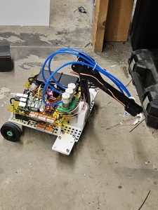
Sunday night, we discovered that our belt drive could not work with the motors that we bought with our project. As such, we switched to using casters on the front to facilitate smoother driving. With the nature of the casters, rotation is now inconsistent. What that unfortunately means, though, is that we’ll need to do feedback with the camera movement and switch to only using the DC, non-encoder motor movement. I designed the holders for the casters and we mounted them Wednesday night.

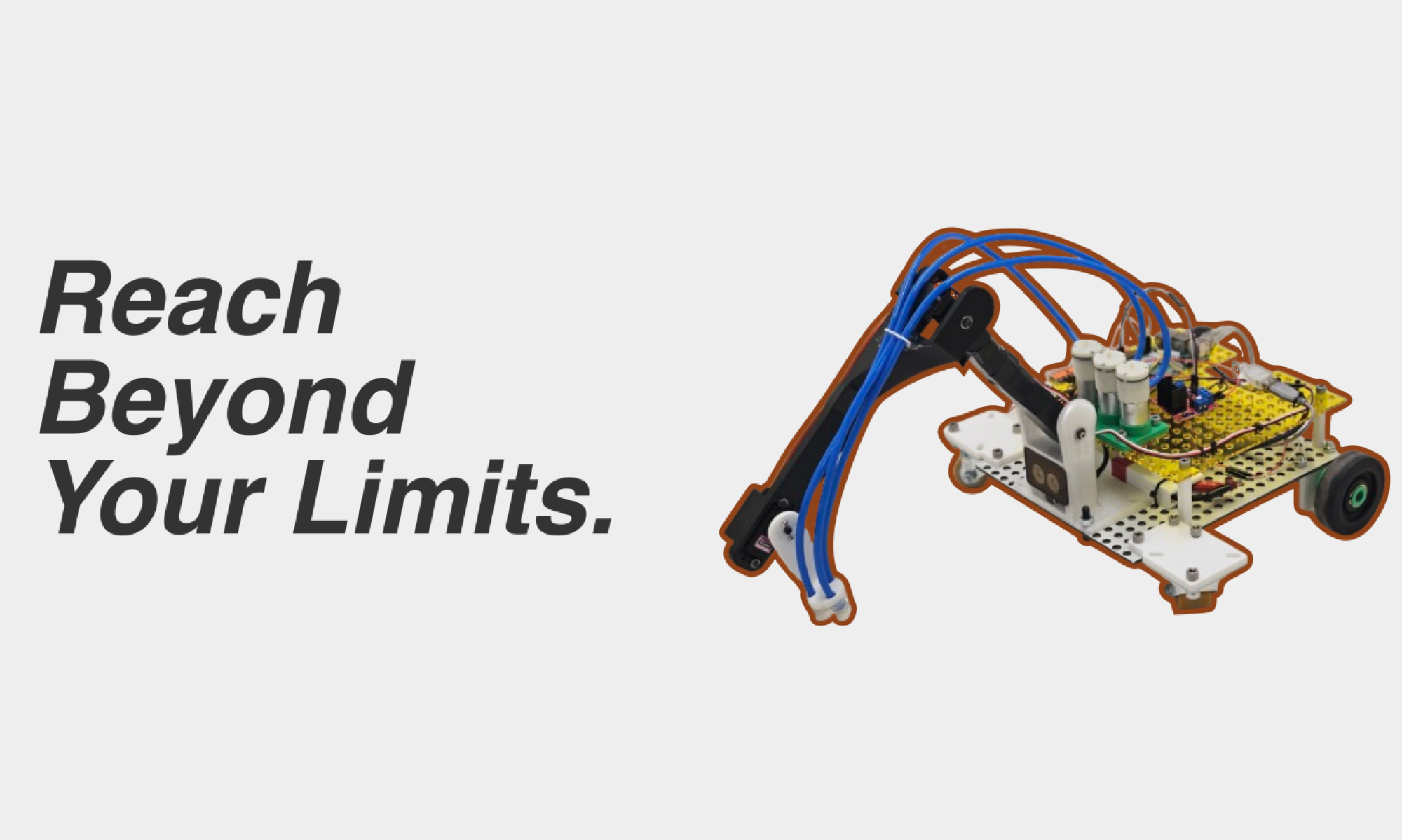
Wednesday morning, still unfortunately, we discovered that post-manufacturing, one of our servos had broken, likely from human misuse. What that meant was that I needed to rebuild some of the arm. It was at that time that the heat-set inserts in our arm began to fall apart, and the arm itself began to become undone. After verifying that our rover could drive more smoothly late Wednesday night, I verified once more that one of our servos was broken on Thursday, and debated a redesign. Unfortunately for my sleep schedule, I saw quite a lot of improvements that could be made to the initial design, and began work on redesigning the entire robot front end. By early Friday morning, the new and improved HomeRover was designed:

A couple of things that you’ll notice- a lot less moving parts were on this arm- with Roboclub’s fast-moving Bambu Printers, print times for each of these were a lot less than I expected. The camera is now at the x-center of the Rover. This is very important. Now, when we align with the object of interest, we don’t need to do more complex math and can now simplify our kinematics down even more. The arm is a lot more structurally sound. Double supported bearings on more critical joints allow for smooth movements. Now I hear you asking- Varun, is this going to add another two weeks of manufacturing time to HomeRover?

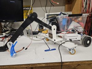
Nope! In less than 24 hours, fast printers and pre-established tolerances allowed me to fabricate the entirety of the new and improved HomeRover arm. Today, I sourced the rings that hold the wheels in place (so they won’t fall off so much). I positioned the servos such that they would not break at rest, and improved the servo at the end of the arm so that it can manipulate the final iPad more efficiently. In the end, we have a much better arm that will be more consistent. Touching on verification- I need to make sure that our arm moves consistently. While tuning our kinematics with Nathan, I need to make sure that things will not move differently than on demo day, so I will be testing the entire subsystem soon.

Great, so now we have a robot arm that is theoretically consistent, but we really need to get it to move consistently. I’m working on that too! Now that our problem has been exponentially simplified by the redesign, I was able to get my hands on a script that does that calculation for us.

With some very simple trigonometry, we have the AB and BC angles (shown above) that lead to distances that we need. Verifying our initial range, we wanted about from 10-30 cm away, and we have 11-36 cm away (according to these calculations.)

All this is very great, but I need to get the kinematics actually implemented. That’s a tomorrow issue 🙂

We are no longer nearly as behind as I thought we would, especially because the refabrication allows for that aforementioned simplification. By next week, I want to essentially have the HomeRover barebones functionality done, and I think it’s possible. By tomorrow, my goal is to be able to send the Raspberry Pi on the Rover a Y and Z coordinate (manually), and have the arm traverse correctly to that point and initiate the “pumps” (by printing out “I AM PUMPING” repeatedly into the terminal.)
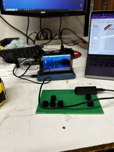
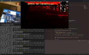
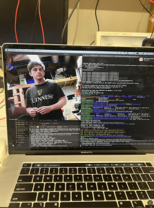
Hayden’s Status Report 4/6/24

This week I spent four hours on Sunday debugging our communication protocol and establishing connection between the controller and the rover to allow driving to be demonstrated. After we achieved driving functionality and demonstrated I worked on rewiring and cleaning up the rover to make sure we will be able to fit everything on it. This week was heavily based on verification for me because I have completed the subsystem that I was in charge of. As far as verification I checked the latency of transmission between the two computers and found the latency was consistently less than 100ms which meets our design requirements (averaged about 15 ms, not sure if I measured properly but I count this as verified). I ended up putting a set delay/latency of 10 ms in the Python code just to make sure everything between the two systems was consistent; without this delay we had some interesting bugs.

As far as the latency of the direct wiring on the rover and in the controller I used the slowmo function of my iPhone 14 pro which has a frame rate of 240fps which allows us to detect latency to approximately 4ms. From this test I was able to confirm that the latency was below 20ms in both cases with the key press reaction being approximately 10ms (limited by the frame rate) and the rover motor reaction, which I ballparked by looking at the approximate time it started driving, to approximately 15ms. While I am not entirely convinced the measurements are the most accurate they are good enough for the design requirements we have outlined. I also scaled down the board size of the PCB and I am trying to source a Raspberry Pi 4 with greater RAM because that seems to be the bottleneck for the speed of the controller (I tried using different power sources, different WiFi connections and downloading different operating systems and the python code still was running too slow).

Given that the subsystem I was put in charge of ended up being much less involved than we initially expected I will be spending the rest of the time working on the arm kinematics with Varun and verifying the suction mechanism works as intended. We plan on verifying this system by lifting actual objects with the suction and making sure the servos and 3D printed components are strong enough to hold up to the weight of an iPad. I do not foresee any necessary schedule changes since we updated our Gantt chart and have cut time on certain tasks. I found a Raspberry Pi monitor I think will be perfect for our controller and is in our price range; I will place the order this week.

In the next week I will work with Varun to finalize arm movement and suction and begin system validation tests such as driving to a location and pressing the pickup button.