Team Status Report for 4/27/24

We have officially completed all parts of our system so the only risk right now is if we cannot configure the system effectively to meet our pickup accuracy. We have been working hard to tune our system to detect items correctly and position itself to pickup; however, we are yet to find the sweet spot in our configuration that gets us the 80% threshold we want to achieve. The current contingency plan is to keep tuning it until it can detect the item correctly; we are experimenting with a few different item detection models still.

This week we reverted our design back to having the logic level shifters as well as a PMOS switch so we could reach the 7.4V input to the pumps. Through experimentation we proved that 7.4V was necessary to achieve our pickup weight of 700 grams. We will also be adding some extra weight to the rear of our design to make sure it does not tip over. Nathan is also working on developing a web page we can host with the camera feed; we found that this was the most effective way to be able to relay the camera feed back to the user side.

Here is the camera feed working.

Unit Tests Performed:
User Side Latency –> 10 ms Passed (5 trials timed/slomo camera)
Transmission Latency –> 15 ms Passed (5 trials timed/slomo camera)
Rover Side Latency –> 10 ms Passed (5 trials timed/slomo camera)
Lifting Capabilities –> 500 grams Failed –> 850 Grams Passed with 7.4V
Driving Speed –> 0.24 m/s Passed (5 trials measuring drive time across 1 meter)
Lifting time –> 8.4 seconds (calculated by timing lift across 70 trials)
Detection Accuracy –> 64% ish (calculated by 45 successful trials across 70)
Battery Life –> 1.25 hours of capacity (measured how much time we were able to perform tasks like driving/pickup)
Item Detection Range –> 33 cm (placed objects varying distances and found the maximum bound)

Team Status Report for 4/20/24

For the past two weeks, the main thing we as a team have been working on revolves around integration and connecting together all our separate subsystems.  When connecting our object detection/depth map code that instructs the motors to turn and move a specific direction, we ran into difficulty parallelizing the two processes, either using Python’s multiprocessing and socket modules. The two control loops were blocking each other and preventing us from progressing in either program, but as stated in Varun’s status report, the end program is an overarching one acting as a state machine. After fully assembling the rover and running integration tests that involve the full pipeline of navigation -> detection -> pickup, the most significant risk lies on the detection side. Earlier in the week, we were running into an issue with the coordinates that the object detection pipeline was giving for the bounding box it created in that the y-coordinate it outputted wasn’t necessarily the top of of the object, but the center relative to some part of the camera, causing our suction to undershoot because of inaccurate kinematics. After investigating the various dimensions and y-values that exist in the code and comparing them to our hand measurements, we found that the detection.y value it spit out did reflect the top of the object, but regarding its magnitude, it reflected the distance from the bottom of the camera. To mitigate and manage this risk, as well as improve our kinematics in the process, we plan on finetuning a potential hard offset to all y values to ensure that we hit the top of the object as well as tuning with adding a variable offset based on the bounding box dimensions. We have started doing this, but plan on performing a lot more trials next week. Another risk involves the accuracy of the object detection, which meets below our standards as defined in the design and use case requirements. A potential cause for this issue is that since mobilenetSSD has a small label database, there’s a chance it doesn’t encompass all the objects we want to pickup, but since we don’t necessarily need identification, just detection, a potential risk mitigation strategy is to lower the confidence threshold of the detection pipeline to hopefully improve on detection accuracy.

One change that was made to the design of the system was adding a second layer to our rover to house our electronics due to space constraints. The change does not incur major costs since the material and machinery were both provided by Roboclub. This is a quick, lasting fix, with not further costs needing mitigation going forward.

As stated in our individual status reports, we are fairly on track, with no major changes to the schedule needed.

A full run-through of our system can be found here, courtesy of Varun: https://drive.google.com/file/d/1vRQWD-5tSb0Tbd89OrpUtsAEdGx-FeZF/view?usp=sharing

Team Status Report for 4/6/24

This week we accomplished a lot; we completely finished the driving subsystem with the controller and we were able to start verification of this system. We had to revamp the driving because the motors were under powered and we also revamped the robotic arm to position the camera in a central location to simplify the task of alignment. These decisions to change the arm and the drive train was to mitigate the risk of time. The largest risk we have right now is that we are unsure if we will have enough time to properly verify and validate our design once we complete it. We also broke one of the servos and luckily we have a spare but frying another one would be a major setback when we have to wait for delivery. We updated the Gantt chart last week and we are feeling much more confident about our timeline; as we have been working some things have become complex and others simpler than we expected.

Verification has occurred for driving and controlling and we will begin verification for the arm this week. As far as full system validation we plan on driving the rover this week and trying to pickup items when we align the rover properly using our own vision. We will not be incorporating the camera just yet but we will be driving blindly to work on fine tuning the object detection. For validation of our proposed latency, as Hayden mentioned, we’ll be using a high frame rate camera to check how long signals take to go from button press to robot movement. So far, the movement has been pretty close to instantaneous, so we haven’t needed to worry about it too much. In terms of drive validation, we have validated our drive- the Rover moves in the fashion that we intended it to, and can connect from quite a distance and remain relatively seamless in operation. As Varun mentioned in his report, we’ll be verifying consistency of the arm subsystem by power cycling the rover and determining with a vertical marker if the Rover got to the correct Y and Z positions. After that, we’ll begin working to bring the separate systems together. Considering the simplification that the new arm brings, we should be pretty solid in terms of progress.

Biggest risk right now is the Servos breaking in testing, causing a large lead time to get new ones. The contingency plans are to switch to a smaller, more common, high-torque servo for the second stage in case this servo breaks. Quite a lot of changes were made to the overall system to better facilitate testing- however, the overall block diagram has not changed this week.

(HomeRover’s overarching redesign!)

Team Status Report for 3/30/24

When we were all working together on Friday, one issue we noticed is that after switching to the 5V driver from the Arduino Nano, when spinning the motors, we observed that they were not spinning the same speed. This is a significant risk in that if there is disparity between the motor speeds, because of our belt setup,  it would affect the manner in which our robot turns, making it not dependable or reliable. To mitigate this risk, we have two potential avenues to pursue: the first is through tuning the commands given by the microcontroller to make sure that the robot can indeed drive straight, thus allowing us to maintain the same speed for the motors manually through tuning. The second way of mitigation is through using rear wheel drive only and switching to casters on the front wheels. This is because the belt tension is causing undue force on the motor shaft, causing it to spin slower. If we convert to rear wheel drive, it removes the need for a belt in the first place.

A change made to the existing design of the system is the switch from using a Raspberry Pi Pico to an Arduino Nano. This is necessary because it allows us to drive a 5V logic as opposed to a 3.3V logic. The change does not incur any additional cost because the Arduino Nano was provided free of charge.

For an updated schedule, we are hoping to target this week to be able to drive the rover and control the servos for the arm, even if it’s a basic program to test functionality.

This video link showcases our currently assembled rover so far (sans-camera), with the motors successfully wired up and spinning!

https://drive.google.com/file/d/1zICyOJkQBSxv6ApgS1hE1o7wqdp9SjWX/view?usp=sharing

Team Status Report 3/23/24

As of right now the biggest risk that could jeopardize our project is the integration of the control system on the rover. We officially have a rover built but we need to integrate the electronics onto the rover which is going to require a significant amount of work. Our current contingency plan is to put our heads down and write code for the next week so we will have a working system prior to the interim demo. We don’t need to make any changes at the moment because we have 3 weeks of slack time built into our project timeline and with this we have two more weeks to get a semi-working integration of the rover then 3 weeks to improve the accuracy of our model. We see the claw kinematics and the object detection as the one thing that we are going to need to tune the most and we believe that three weeks is adequate time to achieve this to a reasonable degree.

There were no changes made to the overall design of the model, just some changes while fabricating that were planned. We added a slot that allows for the adjustment of the deadshaft wheel in the front, so our belts remain tightened.

The Rover in its non-electronic-burdened form!

Team Status Report for 3/16/24

After doing a post spring break evaluation, the most significant risks that could jeopardize the success of the project revolve around the camera, both in terms of its function and the dependencies that require its outputs, such as the kinematics calculation module. Despite having a pipeline that can detect depth and display a live camera feed smoothly on my (Nathan’s) laptop, when using X11 forwarding, the resulting feed was extremely slow and laggy. Our plan to manage and mitigate this risk is to get our RPi monitor as soon as possible to test on actual usage as well as look for any opportunities to lower bandwidth and latency. The Luxonis documentation has benchmarks to test these values so we can analyze if we have any shortcomings. Additionally, another risk that stems from the first risk is the fact that we are behind on our timeline. However, we have recently placed orders for pcbs this week so for these fabrication tasks, we have controlled what we can control in terms of timing. This week saw a lot of fabrication of parts, so our next weeks will see an abundance of integration and in-person meeting time.

No changes were made to the existing design of the system and it is consistent with the change made after spring break.

Although no official changes to the schedule have been made, we are systematically cutting things out from the future and trying our best to push forward in terms of days.Here are some parts Hayden and Varun made!

Team Status Report for 3/09/24

The biggest risk, which I (Varun) only realized while testing, was whether or not the suction cups could even hold up an iPad. Thankfully, that risk was provably mitigated. Currently, the most significant risk is the kinematics. We’ll need to update the previously thought-out kinematics to be slightly more robust (described in our design report). I hope to figure that out this coming week.

We changed the block diagram of our system a bit, to account for said kinematics. We’ll need fast encoder feedback, which can really only be done on bare metal microcontrollers, rather than the OS-stuffed Raspberry Pi 4. We updated our block diagrams to reflect this change. It adds the cost of the Raspberry Pi Pico, which is rather minimal. Varun’s status report has the progress of the suction system!

Part A – Varun: 

Our target demographic is, by design, people who are not technologically savvy. As mentioned many times prior, the inspiration for this project came through Hayden’s grandfather, whose capability to move is rather limited. Also limited is his technological ability. As such, we decided to simplify the control sequence to ensure that people whose technological ability is at the same level can easily use HomeRover. Additionally, the automatic sequence to grab an object is easily reachable by the touch of a button, so users don’t have to spend a lot of time to learn how to use our system. The factor we want to touch is one that is not talked about much, which is recovery. Though recovery is extremely important, it is a part of the process that is hard to suffer through. We aim to ease that suffering just a little bit, with HomeRover.

Part B – Hayden: 
In regards to different cultural factors our design is robust in a manner that does not require a written language. Our control center uses four buttons for controls which will be labeled with arrows and two buttons for interacting. The two buttons will be labeled with icons that can be translated in a user manual to make the design usable by all cultures. The monitor will display when the rover is in the proper range to pickup the item using colors; red and green are seemingly universal for good and bad so we are employing these colors on our display. As far as moral values in religions our design uses ethically sourced materials and we are mitigating waste by using our modular design. As far as traditions and laws, the only groups I can think of that we are violating their beliefs with our design are the Amish and Mennonite communities; these groups are not in our target demographic so our design is sufficient culturally.

Part C – Nathan:

Considering environmental factors, especially when pertaining to our design’s relationship with living organisms and natural resources, we are primarily concerned with the sourcing of our parts. Because our design utilizes LiPo batteries on both the user side and control side, we have to be cognizant on the origins of the lithium, and by extension the cobalt, that goes into these rechargeable batteries. According to Siddharth Kara, “roughly 75 percent of the world’s supply of cobalt is mined in the Congo”, and oftentimes this is by the hands of child labor. If we are not aware of the origins of the cobalt that go into our batteries, we are directly supporting these brutal mining practices that are causing both human and environmental catastrophe through the exploitation and exhaustion of the natural resources of the Congo land. This is an environmental consequence of utmost importance and it will be considered heavily when purchasing the parts for our system.

Team Status Report 2/24/24

As of this past week the biggest risk we have identified is our development of a power distribution board. The biggest risk is that no one on our team has experience with this type of design. Hayden and Varun are working on this design and have been reading data sheets for the components we settled on for our electronic scheme. The current contingency plan is to start early and get help from people we know that have experience in the development of power distribution boards for systems. One change we’ve made this week which was not reflected in the block diagram in our Design Review presentation was that we decided that using an Arduino Uno would simplify the pcb design for the user side because we can use it to convert to USB protocols. This change does not incur any costs because we already have three Arduinos from previous classes. We spent a lot of time this week discussing what libraries and types of software we want to use with the camera. We had a slight hiccup where the software for the camera was not running for a little bit but we have resolved this issue. While we have not made an official change to the schedule just yet, we might have to add an additional week after Spring Break to finish up fabricating the rover. The CAD design is finished! See below.

Team Status Report for 2/17/24

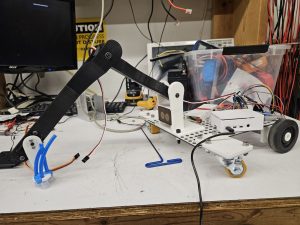
Currently, the most significant risks that could indeed jeopardize the success of the project are the actual suction mechanism reaching the desired target, and the vision of the objects. As we have successfully obtained the requisite depth camera, we will be able to begin actual work in experimenting with the hardware itself. In this way, we should actually be able to finish with the identification and location of the objects. Our concern, then, currently lays within the kinematics to reach the desired object. None of us are experienced in the kinematics side of robotics, mostly with fabrication, so we have deliberately stuck to a very simple, DOF-limited robot arm on the front of our robot that indeed should be easy to calculate with. There are many YouTube tutorials, and with the scheme that we have chosen, we already found an easy way to implement the kinematics. The devil, however, is in the details. We’re concerned at the moment about the physical implementation of these kinematics. Of course, we imagine that we’ll be able to tweak parameters and effect a change, but we’ll need to ensure that we have time to sit and tweak to ensure that things go smoothly. The block diagram of the system remains the same, but the suction design that Varun envisioned last week is a bit different from what he imagined; now we will use a DC air pump instead of a syringe to create suction. It will be a bit more expensive, but this way, we can ensure that the amount of pressure will be sufficient. Here’s a much more complete view of the draft version of HomeRover:

Part A: Varun
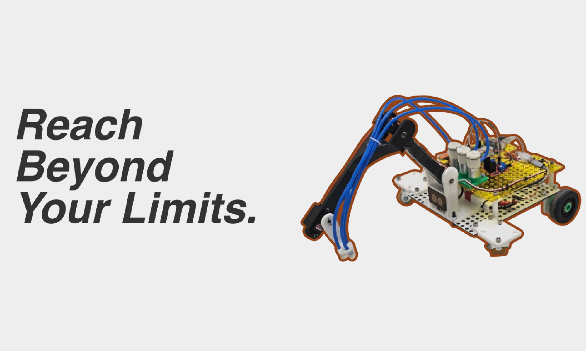
HomeRover, within the concept itself, is designed to meet the psychological and physical needs of those who are afflicted by a lack of mobility. Therefore, the consideration that we target is that of public health. As enumerated before, the purpose of the project is to exist such that someone who is essentially stuck in a chair can use it to grab objects around them with relative ease. As we mentioned during our proposal presentation, this idea came about due to a struggle that Hayden’s grandfather was facing. As he had recently broken his hip, he found himself stuck in a chair, with a small meter-long grabber that could not aid him to grab objects that were farther away from him that what his arm could reach. (that’s where our slogan, Reach Beyond Your Limits, comes from!) We saw an opportunity to consider his psychological and physical health, and we knew that we needed to take it.

Part B: Hayden
As far as social factors, our target audience is the elderly and our design has to be intuitive and fairly simple. We know that our design needs to be easy to use by people with minimal education on modern technology and computers, which is why our design includes a basic arrow key control system with a monitor. An additional social factor we need to consider is that older people are sometimes untrusting of new technology and might not want something like HomeRover in their home; while furthering our design we need to find a way to ensure our customers that we are not collecting data or violating privacy within their home. Lastly, when it comes to our target demographic we also know that people are more financially conservative when they are older; because of this, we have made our design as inexpensive as possible by 3D printing parts and designing our system on Raspberry Pi’s that can compute fast enough but are not super expensive.

Part C: Nathan

With regards to economic factors, the first of which we have considered is that of the system of production, specifically supply-chain availability. When deciding on Raspberry Pi’s for our main source of computing capability, one aspect we considered was whether or not there was a shortage in most major retailers. However, according to multiple websites and news sources, the shortage seems to be resolved, indicating that we would be able to produce units cheaper. As a result of this, we can reduce the overall cost of our product, appeasing our target demographic who are more financially conservative, as aforementioned. In addition, because we are 3D printing parts, there is less pressure on sourcing parts through distributors and jumping through the hoops of retailers; the agency in building and representing our design tangibly is in our control, not on the onus of third party manufacturers.

Team Status Report for 2/10/24

This week, we delivered our proposal presentation. The feedback we received from the presentation was mostly about the presentation itself, so we didn’t make any change to the design from the feedback. There have been no changes to the requirements of the system; it seems that what we had for the presentation with our initial goals should be valid for the future as well. However, based on input from more experienced roboticists advising us against it for the purposes of the timescale of the semester, we made the difficult decision to abandon the intended Rocker-Bogie Suspension system (pictured below), and switched to a more common, easier to implement and calculate feedback with, four-wheel tank drive.

source

The biggest risk that we believe right now is the design of the software-side kinematics, in tandem with the hardware. As of current, we have on lend from the ECE department the RealSense L515; despite the initial plan to use the OAK-D SR depth camera. This weekend, before Monday, our goal is to finalize whether or not we will be able to order an OAK-D SR camera. Most likely, we should order one, but we want to make sure that the overall cost of the robot doesn’t get too high, and that we don’t spend all 600 dollars in one shot.

We have not made any changes to our schedule; we are currently on-target based on our initial Gantt chart, but we need to make sure that the design presentation does not impede the flow of work for the rest of the project.