This week on the project, I helped integrate the Raspberry Pi program that successfully receives button presses serially from the controller and simultaneously transmits the results serially to the Arduino Nano that controls the turning of the motors. In addition, I integrated the camera onto the rover and did minor calibrations to the camera control loop based on realizations after mounting the camera to the rover.
After demo day, I witnessed some other groups have computer vision follower-based ML systems, and one group was using the Yolo v8 architecture. I heavily considered the idea of using a Yolo framework over a MobileNetSSD framework due to the increased variety of objects it can detect (# of labels) as well as potential higher accuracy due to using BGR frames rather than black and white frames. This meant that I had to figure out the longstanding issue of the ColorCamera never being recognized. I finally figured out the solution to this issue: in various example programs, the default configuration of the camera and the socket that is used, called “RGB”, is not present on the Oak D SR. Thus, to fix it, I had to manually set the socket port to CAM_B or CAM_C, and rgb functionality finally worked. However, I was having trouble setting up a Yolo architecture because it required both an rgb socket in use as well as left and right stereo camera. Originally, they were MonoCamera, but this conflicted because we had three different cameras needed but only two sockets. Thus, I researched how the StereoDepth feature worked further on the Oak D SR camera and found a workaround which was to use rgb ColorCameras for the left and right cameras necessary for depth detection, as well as to “align depth map to the perspective of RGB camera, on which inference is done“. The tentative code that I adapted can be found here: HomeRover Github
The Github also includes the rover control arduino/python code written for intersystem communication.
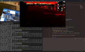
This photo shows the openCV frame that captures an rgb image output, something that was so elusive to me for so long, along with the corresponding depth heatmap.
My progress is on schedule despite the revamping of our object detection system. It is aligned with the developments made to the kinematics scheme in that the communication between the camera control loop and the arm control loop needs to be established, which is what I hope to complete this coming week. Since there is no cross-device communication for this, I hope it is easier than serial communication between different computers like a few weeks ago.
The tests I am planning to run are twofold and involves testing my individual subsystem and integration testing. For testing my individual subsystem, I aim to keep a few big concepts in mind that define our use case and design requirements, that of versatility and accuracy. I hope to gather a variety of objects, and with the camera mimicking a position like on the rover (lifted off the ground with a similar background setting), achieve accuracy up to our requirements for both object detection and transmission of accurate signals for directing the rover. Further tests to ensure accuracy will be made in conjunction with incorporating the arm in that the coordinates passing and translation constitutes an important part of our system. In addition, I hope to perform latency tests with my control loop code running on the RPi in using slow motion cameras to identify the object detection reaction time to an object appearing on screen to make sure it falls within our requirements for appearing instantaneous.