What did you personally accomplish this week on the project? Give files or photos that demonstrate your progress. Prove to the reader that you put sufficient effort into the project over the course of the week (12+ hours).
This week, I mostly worked on physical aspects of the system. I soldered the 200k resistors to a board (old design) to test mic gain; it’s difficult to tell if the result was an improvement, because oscilloscope/output pin testing was marked by drifting output values and the Beetle or mic overheating. As it turns out, the overheating was likely due to an issue with the mic connections, not resistor values. I also tested if the Beetle could function with battery power alone (not connected to a computer), and got it to respond to pressing the button intended for mode selection. Using https://docs.arduino.cc/built-in-examples/digital/Button/ and Freda’s code from https://courses.ideate.cmu.edu/60-223/f2022/work/date-calc/, I also got the Beetle to respond to a button press by changing state. This will be useful when we need to switch between instantaneous and average mode in the final system.
Is your progress on schedule or behind? If you are behind, what actions will be taken to catch up to the project schedule?
Although the deadline of April 24th passed without complete functionality, it should be possible to get everything done by the 30th as promised in the slides.
What deliverables do you hope to complete in the next week?
Since this is due at the end of next week, my overall deliverables are to make sure that the system functions and as many tests are met as possible. More specific deliverables include having a complete and functional file for all integrated code, thresholding the mic output so that LED and transmitted outputs from the mic have some relation to dB values, and helping with remaining tests.
We have legit mic output now, huzzah! It turns out that we needed to solder pins to the Beetle and use a socket to connect the Beetle to the board. Now that the connection is secure, we have realized two things:
The connection wasn’t secure before, and the mic output from before might not have been meaningful.
The mic does in fact respond proportionally to output. The variance can be improved by using a higher resistance value… well, we thought so. It doesn’t significantly improve past a certain point.
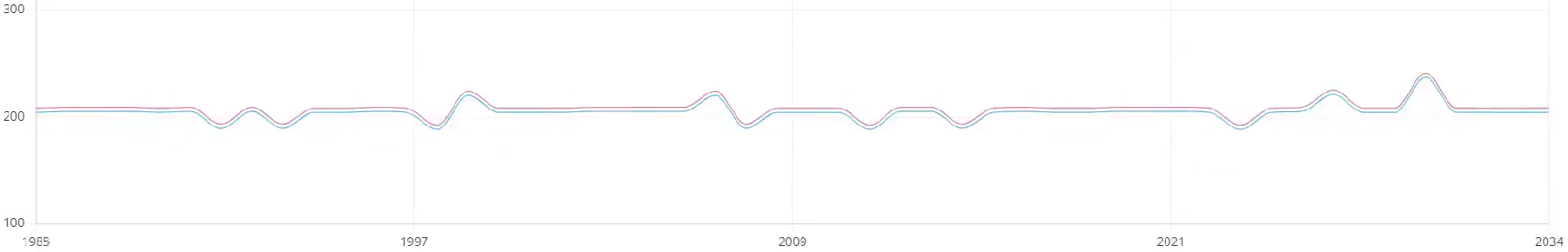
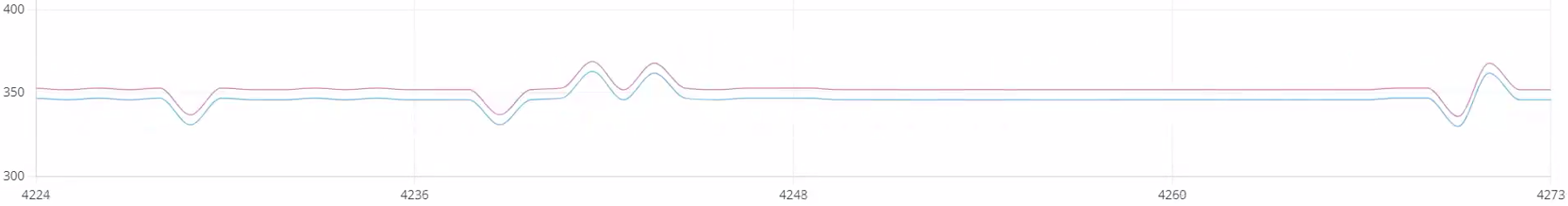
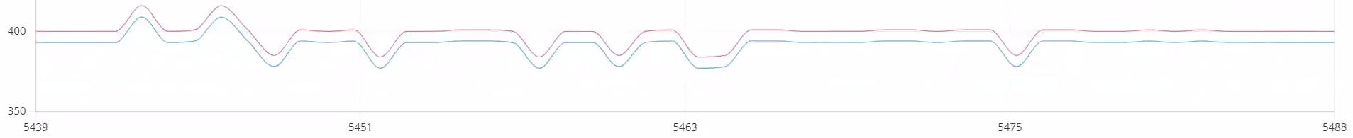
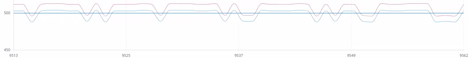
Music studio updates: from testing during one session, we note that the system can pick up on some sounds. The baseline output value seems to drift higher over time. Over the time of 2 songs in the music studio, the input from the tested mic varied within a song by as much as 150 mV. The first song began at approximately 200 mV and ended at approx. 350 mV. The second song began at approximately 400 mV and ended at approximately 500 mV. This effect could possibly be mitigated by introducing calibration.
Beginning of 1End of 1Beginning of 2End of 2
We tested a large range of resistor values, including those greater than the 33k max recommended, in hopes of getting better sensitivity. We tested 50k, 100k, and 200k. The resistance of 200K and 50k were not significantly better/different than 10k. Thus 100K resistors will be used on the new boards since we did have promising potential with those.
This video shows a plot of the mic (above) and peak detector (below) output values as the system responds to music with voice and percussion, using the 100K mic resistor.
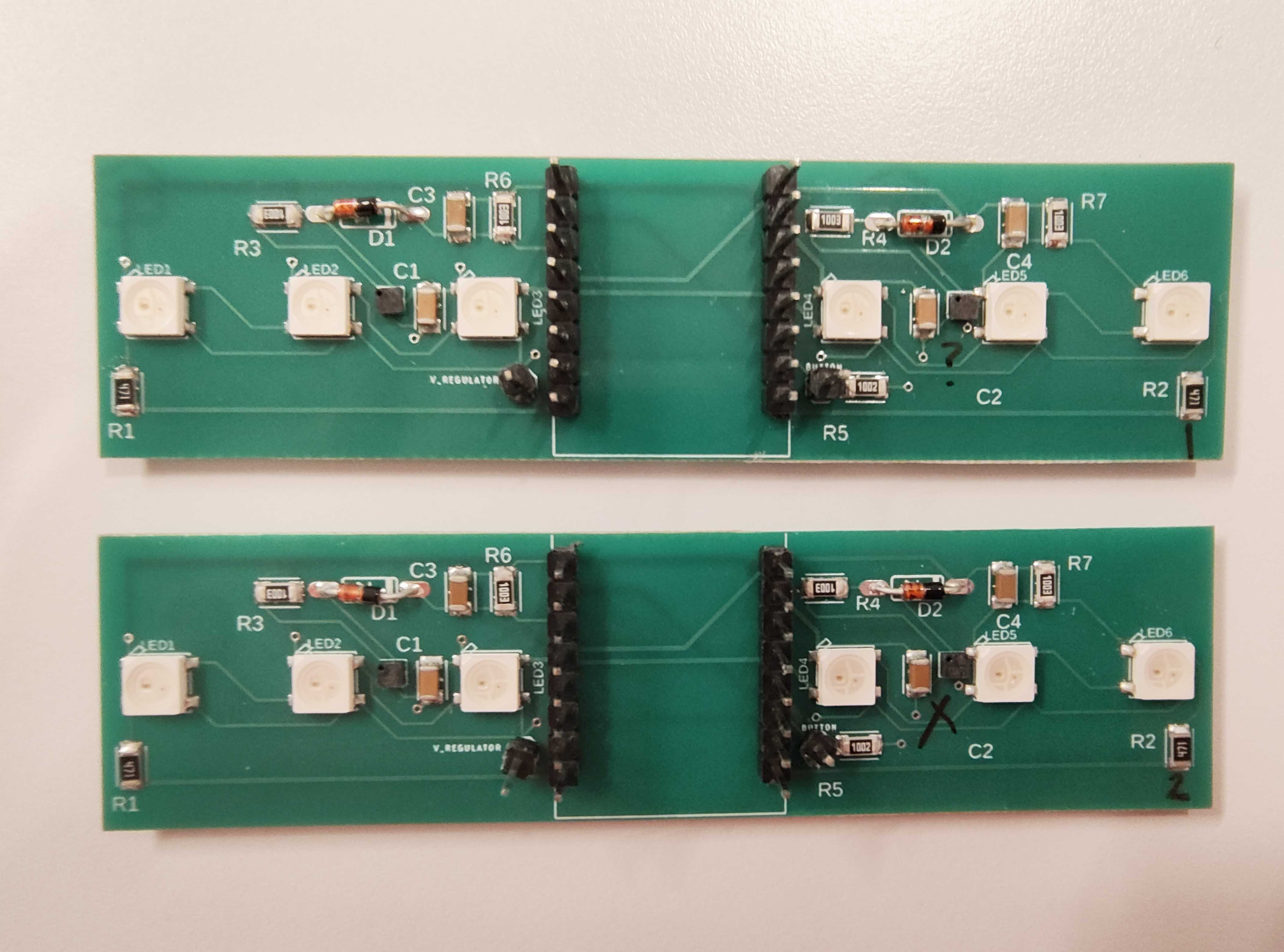
Freda and Lucy also assembled 2 new boards successfully.
What are the most significant risks that could jeopardize the success of the project? How are these risks being managed? What contingency plans are ready?
Significant risks include:
Us not getting the new batteries (Katherine ordered the wrong battery size). This messes with the size requirements we have (although not significantly), and we can still use the batteries we have (and batteries of the correct size have been ordered).
Something going wrong with BLE. Lucy is planning to meet with a person from another group who has experience in order to understand how to get BLE to work. Another risk is that the BLE connection is too slow (can’t match 1-second speed requirement). In that case, we would want to look into strategies to make the code (either bracelet or webapp) create faster results.
Assembly issues. Our contingency plan is to make several copies of the final PCB, both rigid and flex, and to keep the original PCBs as emergency backups.
The Beetle randomly freezes. Is it possible that it is going into deep sleep mode? The plan is to research deep sleep mode and make sure that the Beetle does not go to sleep for the duration of its usage.
Microphone drifts. While the contingency plan is to calibrate microphone outputs at the start of each session, it would be nice to know what’s causing the drift in the first place.
Were any changes made to the existing design of the system (requirements, block diagram, system spec, etc)? Why was this change necessary, what costs does the change incur, and how will these costs be mitigated going forward?
We are no longer doing directionality: the mic location on either side of the Beetle is not different enough to matter. Also, it is hard to solder mics, so it is rare that both L and R mics work for the same board.
When testing the Beetle on the battery, there is not always a response if battery direct output is plugged into BAT, but it will respond if boosted 5V output plugged into VIN (rated for 5V).
It is possible that the system might require start-up time for mic outputs to settle. The mic datasheet says start-up time for a mic is max. 800 ms, but the peak detector at its output might change things.
Provide an updated schedule if changes have occurred.
There are no updates to the schedule. Everything has to be done by the 30th still.
List all unit tests and overall system test carried out for experimentation of the system. List any findings and design changes made from your analysis of test results and other data obtained from the experimentation.
We unit tested the button, lights and mics. Button and lights work fine. As you could probably guess, we’re still having mic issues.
Remaining tests include comparing decibel meter output to system output, as well as evaluating other qualities of the complete system: weight, adjustability, thickness, durability, timeliness, battery life (to be calculated using data from the battery’s output current), and operating temperature.
It may be concluded from our previous remarks that the system test has failed. We are in the process of asking Erin and Prof. Fedder for help.
As you’ve designed, implemented and debugged your project, what new tools or new knowledge did you find it necessary to learn to be able to accomplish these tasks? What learning strategies did you use to acquire this new knowledge?
I needed to relearn how to properly solder things (out of practice). My strategy was to understand that it is possible to improve and that failures can be fixed, and ask for feedback from someone with more experience.
Similarly, I needed to relearn how to program in C++. My strategy was to look at existing Arduino sample code, and run example code to determine if something is a software issue or Beetle issue.
I learned more about how PCB design works (I never helped design a PCB before this semester), including that trace widths are relevant to resistance. My strategy: when reporting results, source the method and calculations so that the logic is apparent to others.
What did you personally accomplish this week on the project? Give files or photos that demonstrate your progress. Prove to the reader that you put sufficient effort into the project over the course of the week (12+ hours).
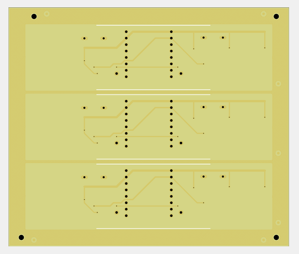
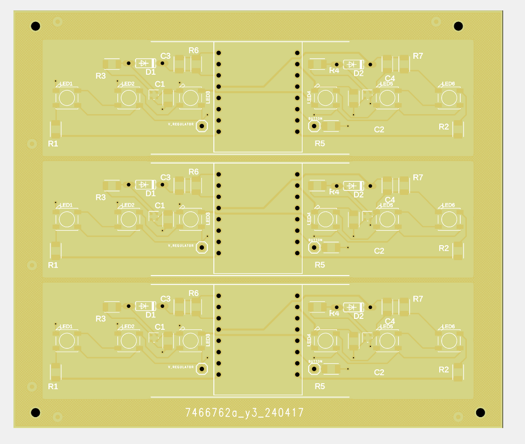
These are details of the panels for the new PCB design.
Tasks from last time are all done except for BLE (Lucy is handling that now), with the caveat that we ended up not needing to order more diodes.
There was an update to the flexPCB order: we ended up ordering both rigid and flex boards, both with the peak detector.
I soldered mic gain resistors with different values to different PCBs and tested the mic responses on an oscilloscope (for values of 0, 10K, 33K ohms). This confirmed that 10K is sufficient for gain, which means the final design can use SMD 10K resistors. This should make final assembly easier.
I verified that PCB trace widths for the new design shouldn’t create problematic resistances.
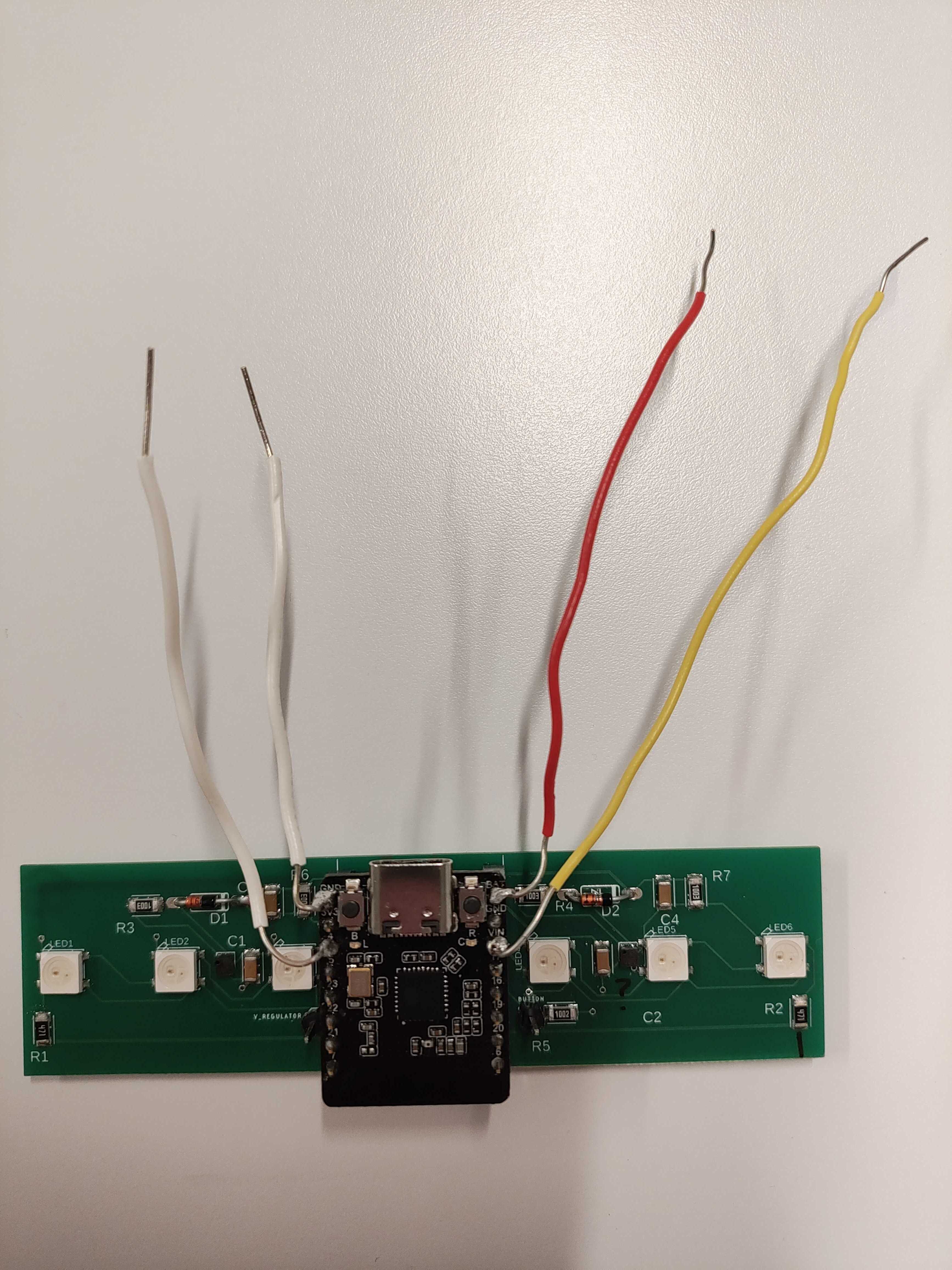
I soldered header pins to the battery breakout board and boost converter so that the battery has a stable connection to the PCB.
Is your progress on schedule or behind? If you are behind, what actions will be taken to catch up to the project schedule?
Progress is generally behind, and I hope to get more work done in the next week so that the final system is functional.
What deliverables do you hope to complete in the next week?
I hope to complete: final mic calibration code, which commands the LEDs to display different colors; button code, so that the Beetle responds when a button is pressed; putting all the code together into 1 file; and getting the Beetle to successfully run off of 1 battery (the connection is stable, but the Beetle doesn’t light up).
This week, we reported on our progress to the music studio in our final visit. We have emailed asking for another session on Thursday or Friday, to hopefully test our final bracelet with calibrated mic values as well as casing.
We started committing by soldering components, which helped determine resistor values so we can switch to SMD to save space. The peak detector circuit is implemented on final (flex) PCBs, and expected to arrive this coming week. We also ordered hard PCBs as a backup in case soldering a flimsy surface goes wrong. All parts for PCB assembly have been acquired.
Our remaining tasks include: BLE, final code for Beetle, mic stuff, and building the bracelet.
For BLE, relating to web apps: we’re using ble-manager instead of ble-plx to connect with the Beetle, and still working on connection and backend. The Beetle is a peripheral for the purpose of the BLE connection.
The final code for the Beetle should include everything we’ve been working on: mic signal processing, LED commands, button input, etc.
Mic signal processing continues. Peak detector values are definitely better, since the peak detector filters out the weird wave pattern we noticed with the previous mic input. One potential issue is that the peak detector output seems to occur in “levels”– almost like high/low values. In order to use this output to command the LEDs, we need to adjust the (one) threshold to be between these two values.
Sorry about the camera quality, but the top 2 moving lines (yellow and gray) represent the values using peak detector, while the bottom 2 moving lines (red and blue) represent values without using the peak detector. As you can see, there are times when the bottom 2 lines are just flat, but the top 2 lines can detect a change, which is promising. The range of values isn’t very large, but could probably fixed with calibration.
In building the bracelet, it was discovered that the pipe from McMaster-Carr didn’t suit our purposes, so we gave it away. We are using multiple overlapping pieces of plastic now.
One remaining issue is that our button doesn’t work. Using the Arduino example code and setup for buttons, we found that the button being pressed does not register. We hypothesize that it might be the Beetle doing internal pull up or down resistors, which messes up the reading because it’s always reading as “off”. One option is to use the example GPIO code for the ESP32, which uses a different method of setting up the button. A back up option exists: we have a header pin, so we can manually reroute to another Beetle pin if necessary if another pin ends up working.
Another remaining issue is that our battery connections are soldered decently but still don’t power the board. As long as this is true, we can’t test the switch for on/off. The cause needs further investigation, but it could be a bad cable.
Our schedule has been updated. The system needs to be functional by 4/24, because that is the day before the first possible day for testing in a music session.
What are the most significant risks that could jeopardize the success of the project? How are these risks being managed? What contingency plans are ready?
The most significant risk is that we do not finish in time. As of the interim demo, web app progress is proceeding well, but hardware is somewhat behind where we expected to be; for example, microphone signal processing is taking much longer than anticipated. This risk is being managed by trying to do tasks that require significant waiting (like ordering parts or PCBs) as soon as possible, and by having multiple versions of the PCB to test with.
The second most significant risk is that the microphone output does not correctly connect to the PCB ADC input, making it impossible to extract meaningful data from the microphone values. This is being managed by implementing a peak detector circuit between the microphone and ADC on one of the final board designs. If this issue is due to loose connections, then the original design on flexPCB will work as expected once everything is soldered together; if this issue is due to some fundamental problem with the mic-PCB relationship, then the peak detector circuit will resolve it. If this is an assembly issue due to how tiny the mic is and how difficult it is to solder precisely, making many boards will help solve it by increasing the expected value that at least one board will end up with working components.
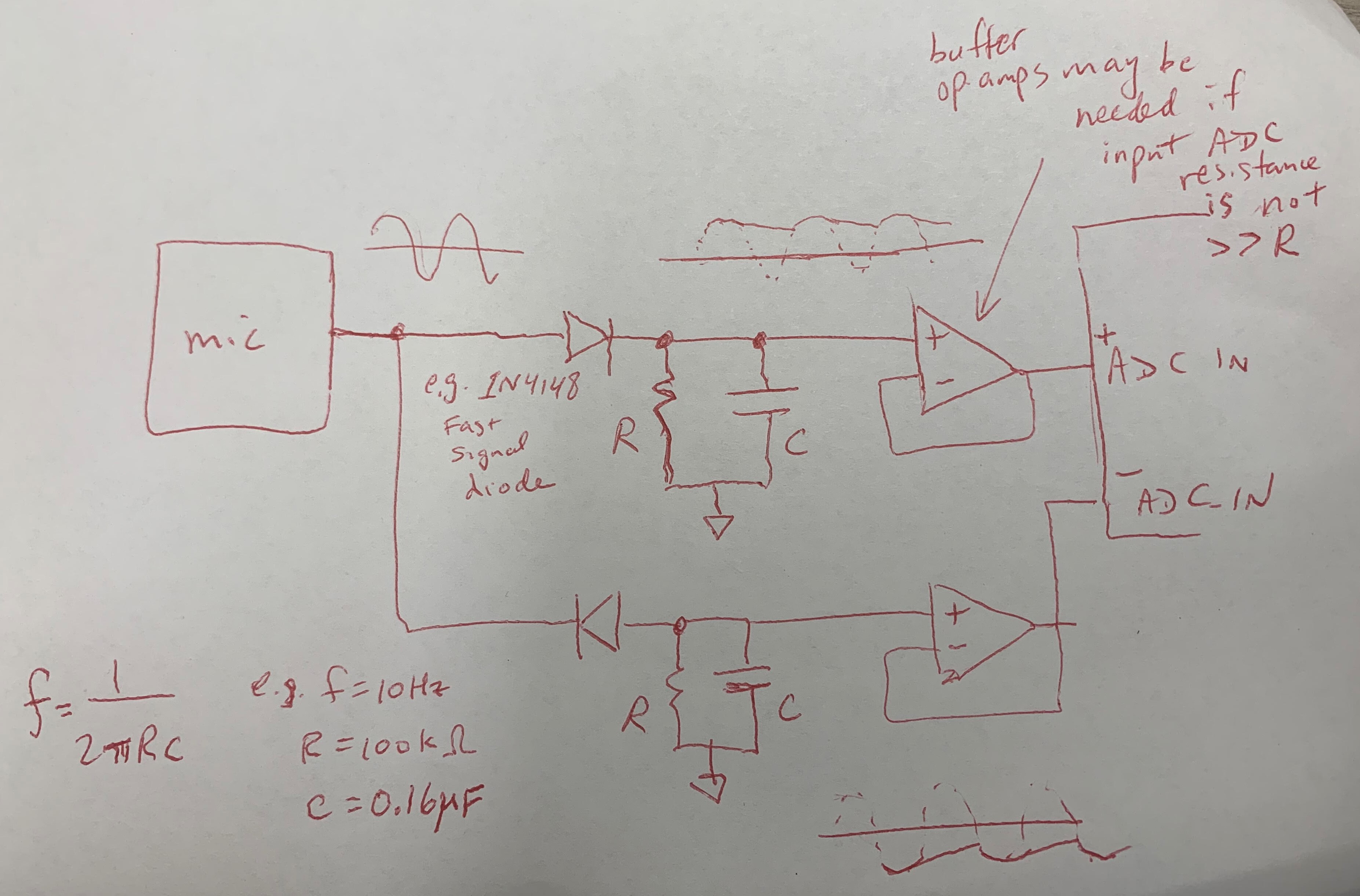
This is Prof. Fedder’s sketch of how the peak detector circuit should be included in the overall design.
Were any changes made to the existing design of the system (requirements, block diagram, system spec, etc)? Why was this change necessary, what costs does the change incur, and how will these costs be mitigated going forward?
Changes were made to the block diagram: for one version of the final design, a peak detector circuit (composed of 2 resistors, 2 capacitors, 2 op-amps, and 2 diodes) now exists between each mic output and microcontroller ADC input.
Provide an updated schedule if changes have occurred.
All code, assembly, and testing must now take place before April 21st. The flexPCBs will be ordered this week.
Now that you have some portions of your project built, and entering into the verification and validation phase of your project, provide a comprehensive update on what tests you have run or are planning to run. In particular, how will you analyze the anticipated measured results to verify your contribution to the project meets the engineering design requirements or the use case requirements? Verification is usually related to your own subsystem and is likely to be discussed in your individual reports. Validation is usually related to your overall project and is likely to be discussed in your team reports.
We have not yet run any of the tests under the explicit rules stated in the design review, because they require either a complete bracelet or a complete mic-LED system. Since the results of each test are directly related to the requirements, considering which requirement is fulfilled by passing each test (with reference to the chart in the design review) should suffice.
This week, I ordered plastic wrap, and failed to establish BLE on the microcontroller. Microphone signal processing continues, but is not yet complete. This is a video of me attempting to test microphone signal processing:
By using a variation of the example code for analogContinuousRead, we can now sample at 20 kHz and above! For voice and piano, this ought to be able to pick up everything but the very highest piano overtones; it also automatically averages the collected samples. I must note here that the datasheet for our analog microphones shows the typical microphone frequency response up to 10 kHz, implying that 10 kHz is the highest frequency the microphone can reliably pick up. The sampling speed could be set higher than 20 kHz in code, but this might have no effect if the microphones cannot interpret signals above 10 kHz.
A greater difficulty exists: as you can see in the video, the microphone input from the continuous ADC read seems to be following a cycle rather than actually responding to the environment. This could just be an error with loose connections that will be resolved when the final product is soldered together, or it could indicate that something is going wrong between the mic output (which is verified to output signals that increase in amplitude as sound volume increases) and the ADC input (which uses example code provided by the creators of ESP32). To be safe, we are going to implement a peak detector circuit for each mic-ADC connection on half of the flex PCBs that will be ordered.
While my progress is technically on schedule in that I have fulfilled the tasks I set last week, I think I am generally behind schedule. I do not think this project will be complete and functional in only 2 weeks if I continue working at my current pace.
Tasks I need to do before next meeting:
Choose resistor/capacitor values for the peak detector circuits
Find instances of the chosen diode (1n4148) and op-amp (LM248) in the Fusion 360 library if they exist
Find datasheets for the chosen diode and op-amp
Order 3 more Beetles, another 100-pack of NeoPixels, and diodes in preparation for assembling the flexPCBs
Place the order for flexPCBs (2 board designs: with and without peak detector)
Verify that a BLE connection can exist between the Beetle and my phone without security issues
Make sure that the microcontroller can send and receive data via BLE connection
Testing status: as of today, I have not explicitly fulfilled any of the tests set out in the design review. I will definitely run the loudness and directionality tests, and will perform other tests as needed. For all tests, including the loudness and directionality tests, the anticipated/measured result directly relates to one of the requirements of the system (as shown in the testing charts on the design review slideshow).
Some of my deliverables from last week are behind schedule. However, the context and importance of some of these deliverables has changed.
Microphone signal processing is done (with Freda’s help) in the sense that microphone inputs can be obtained and used to affect other components like the LEDs. However, further improvement/debugging is needed. For example, I need to look into increasing the speed at which the Beetle runs so that microphone input can catch higher-frequency inputs such as those expected from piano or higher voices. This resource is useful for determining which frequencies correspond to notes we want to catch: https://www.omnicalculator.com/other/note-frequency.
In testing, we are not currently scaling microphone input values to correspond to decibel meter readings. It seems like the scale value varies among microphones, so the best thing to do might be to wait until we have assembled the final hardware components on the flex PCB before tuning the scale values. Similarly, the microphone testing code does not currently average samples over time. Although it is not correct for our final product to register short noises like tapping near the microphone, it is useful in testing. Also, as long as we are not weighting the input based on frequency, it is likely not necessary to perform an FFT for determining the dB value.
Visualization of decibel readings was not complete by March 30th; it is likely that this will be completed after the interim demo.
Some testing of the device has begun. It is not possible to complete the timeliness test now, because the webapp and device are not yet integrated. Similarly, since the bracelet is not assembled, passing the heat test has not happened yet. We are attempting to improve the accuracy of the microphone, but its results do not yet correspond to dB meter readings.
Deliverables for next week include placing an order for plastic wrap, helping bring the hardware subsystem (microphones and LEDs) to a testable state, and testing it in music studio sessions.
Currently, the greatest risk is that we will not be able to extract usable data from the microphones. If this is because the microphone doesn’t react to any sound input as proven on the oscilloscope (likely incorrectly soldered), we can repeat the assembly/soldering process with more components. If the microphone reacts to oscilloscope testing but not to the microphone testing program that prints to the serial monitor, further microphone testing is required to determine the source of the issue. If the microphone reacts to environment sound but the data we receive does not directly correspond to what we expect, we need to continue signal processing to calibrate the data.
We need to have the hardware aspects mostly complete by Tuesday (the first music testing session of the week) and the webapp subsystem mostly complete by Wednesday (interim demo day).
Since last time, we tested the microphones and LEDs on each board to find out which boards have which functioning. We also tested a program that would change the LED color if the microphone input exceeded a certain threshold. Webapp research about the database and file format continues. Also, we now have a decibel meter! This will provide a baseline against which we can measure the bracelet results.
We haven’t changed the design of the system.
The Gantt chart has been updated:
The interim demo is now scheduled for Wednesday, April 3rd.
Database, visualization, customization is due Friday, April 6th.
Timeliness/accuracy/heat tests are also due April 6th.
Caption: The lights change color to red and back to yellow very fast, so if you want to see it better, change the video speed to 0.25, and focus on 0:02 to 0:04.
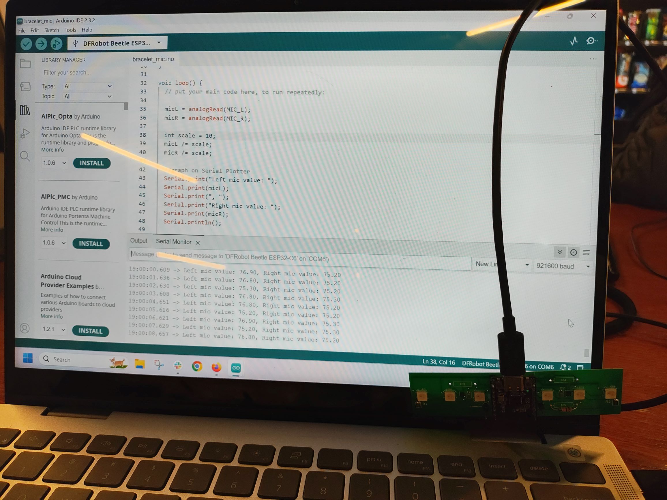
This week, I wrote and tested out a program that relates microphone input values to dB values (multiplying/dividing input by a constant) on the PCB. I can get a Serial Monitor reading of the left and right microphone values that has approximately the right magnitude when the input from each microphone is scaled down by 10.
Unexpectedly, using no resistor (open) in the spaces meant for the gain resistor on the analog microphones returns reasonable values. The values returned are on the order of the values for minimal resistance (when the space for the gain resistor is occupied by a wire).
This photo shows sample results from the microphones without any resistor.
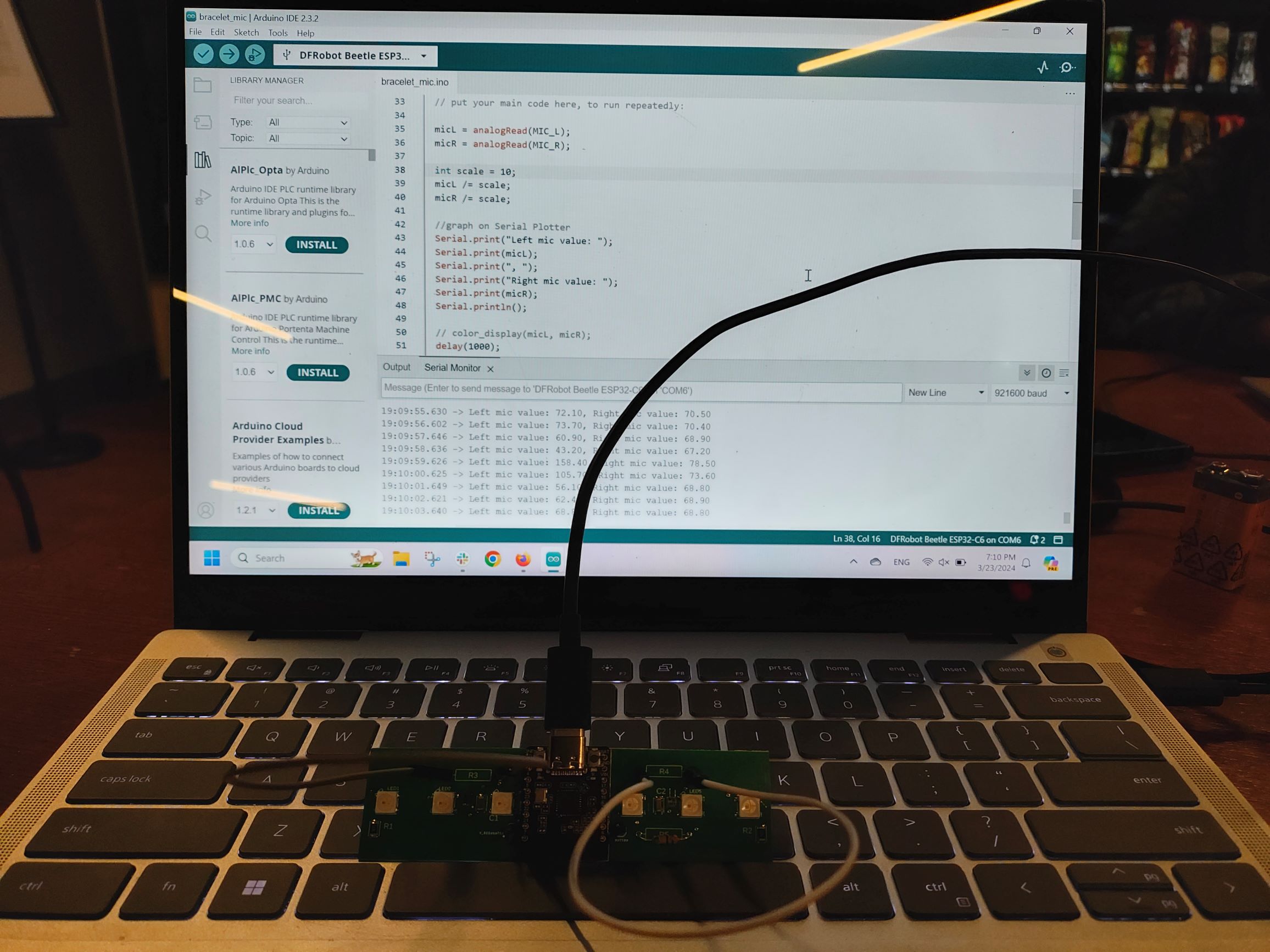
This photo shows sample results from the microphones when they have a gain connection of minimal resistance (wire).
Progress was technically behind on microphone signal processing, the Bluetooth-webapp connection, and visualization of decibel readings. Microphone signal processing is now expected to be complete by this Friday. Bluetooth is most relevant to webapp-device integration, and can be addressed after the interim demo. However, it might be useful to continue searching for resources/information if other tasks are completed early. Visualization of decibel readings is expected to be complete before March 30th.
Most of my tasks this week will focus on microphone signal processing. I’m going to tune the scale that determines output values: gather microphone data from an established sound, measure the sound dB externally, and improve the microphone results by adjusting the scale value to better match the external measurement (thank you, Freda, for suggesting this experiment). I would also like to graph some portion of these results (both from the external measurements and the microphones’ measurements).
For Friday, I intend to update the microphone signal processing code to:
Take multiple samples per second and average or otherwise combine them in order to account for external noise not relevant to the user (for example, tapping the device near a microphone location).
Due to significant differences in different sound apps reading the same sound, we decided to narrow down the variables involved by all downloading the same app and placing votes as close together as possible. We still get different dBs for the same app, but we also have different phones/mics, which we can’t control. The standard deviation between us is about 3 to 4 dB, which is outside of our desired range of being within 2dB of accuracy. The problem is, we don’t even know who is the most accurate, only that we are precise. Luckily, Prof Sullivan offered to give us a more trustworthy decibel meter starting the week after next, which can hopefully clear up this debate permanently. We will be taking it to practice sessions with the music students that we have been coordinating times with.
We also discussed microphone signal processing in our weekly meeting with Prof Fedder. Since microphone noise is negligible compared to the loudness we’re measuring, and we’re only interested in measuring loudness, filtering out noise probably isn’t necessary. A basic version of mic signal processing would measure the amplitude of the incoming signal a certain number of times per second and linearly scale that to dB levels. A more sophisticated version would use an FFT (https://projecthub.arduino.cc/abhilashpatel121/easyfft-fast-fourier-transform-fft-for-arduino-03724d) to see the “spikes” within the frequency range we are interested in, and take the maximum of the spike amplitudes. The problem with either version is that in order to account for frequency overtones and Nyquist’s theorem, we need to sample thousands of times per second. This might be computationally expensive.
What are the most significant risks that could jeopardize the success of the project? How are these risks being managed? What contingency plans are ready?
The PCB doesn’t get here on time (expected arrival Tuesday). Given how much this delay has blocked our progress this first iteration, when we order the final (flex) PCB, we plan to pay extra for fast shipping instead of regular shipping, since we have enough left in our budget.
Were any changes made to the existing design of the system (requirements, block diagram, system spec, etc)? Why was this change necessary, what costs does the change incur, and how will these costs be mitigated going forward?
No changes were made to the existing design. We’re still planning to order a flex PCB with the final design once we have tested the rigid prototype PCB and noted what changes need to be made.
Provide an updated schedule if changes have occurred.
The schedule has been updated. PCB creation/delivery took longer than expected, and a lot of tasks depend on us having the PCB, since a lot of the components are tiny SMD things that we can’t try to do by hand.
This is also the place to put some photos of your progress or to brag about a component you got working.
Here is a picture of the stencil for our PCB.
Gantt Chart changes:
Software: Due to difficulties in getting the Bluetooth connection to work on the mobile app, we have allocated an extra half a week to figuring it out. Additionally, the decibel reading display and visualization algorithms have been moved forward so that they can be done by the interim demo (4/1). Since full integration of the bracelet and the web app won’t occur until after the interim demo, these pages will be displaying information using dummy data.
Hardware: Electronic prototyping/PCB assembly and microphone signal processing have been moved forward by a half-week as well, because we can’t do much without the PCB being physically here.