This week I was mostly invested in experimenting with the mics because those are still not done and I think that’s more important than iterating on the casing.
After our presentation Monday, Prof Fedder met with us to look at the peak detector after the mic output because he thought our graphs looked different than what he expected. Turns out, it was the usual culprit of bad connection due to not soldering things because we didn’t want to make something permanent before we knew if it worked. (Ironically, we would still not know if things worked because the bad connection results in unstable results.) So after I soldered on some female header pins to go along with the male ones on the board, we got some much more stable results on the mic. This led to needing to double check the mic resistor values we used, as Katherine thought there wasn’t much difference between the 10k and 33k earlier, but now we can’t trust that because of the poor connection being a confounding variable.
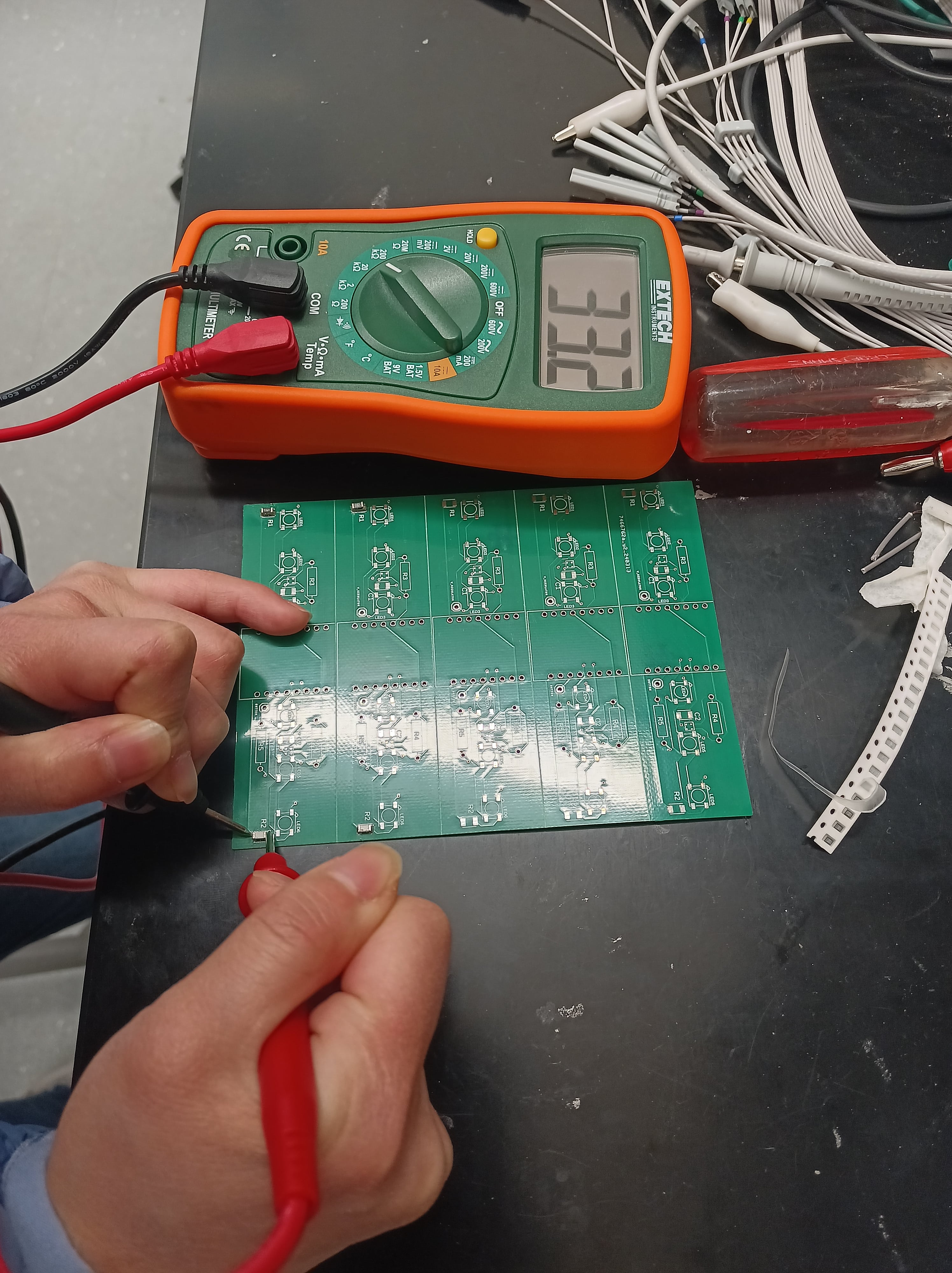
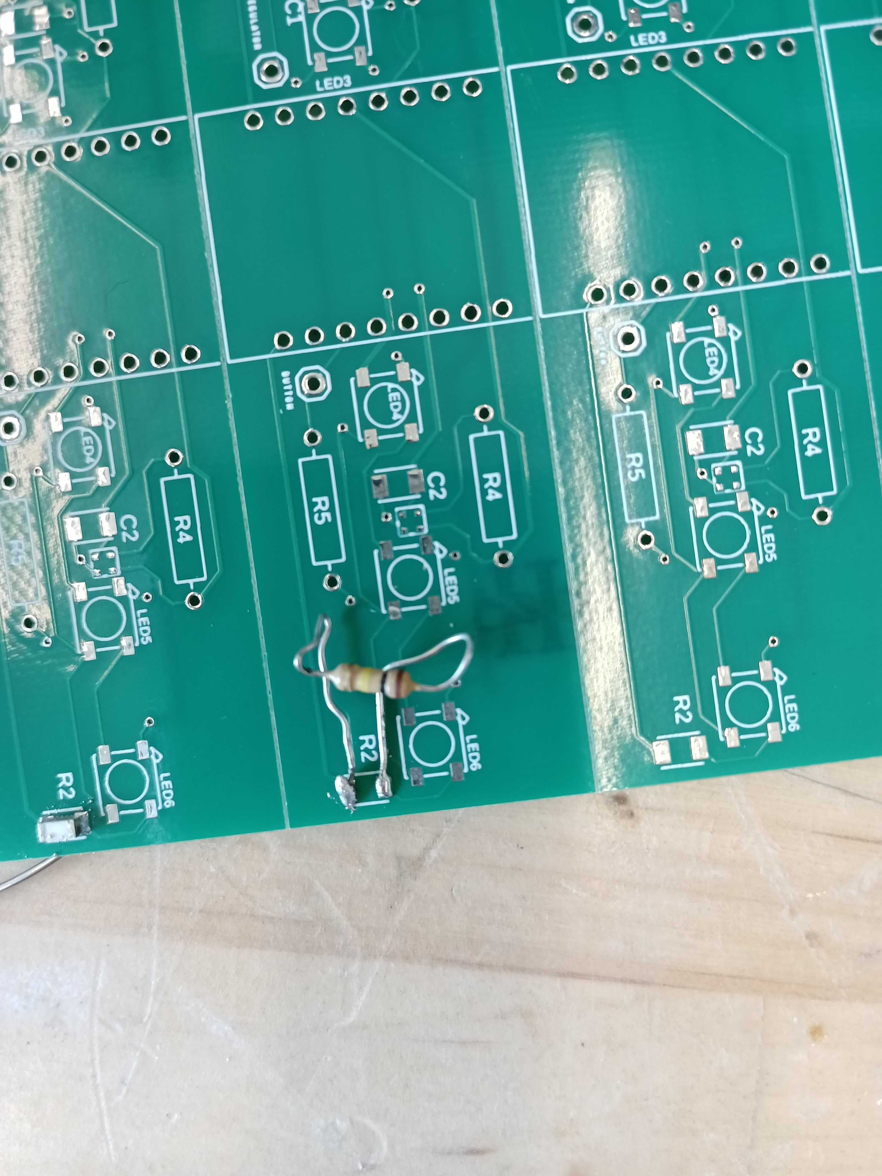
She can probably tell you about those shenanigans more in her report, but the reason it matters to me is because the PCBs were expecting SMD resistors, so if the values in the PCB lab don’t match up with the ideal resistor values, then we were going to need to be creative in order to get that value. For example, the highest resistor value on the datasheet is 33k, but we only have 10k and 100k. In particular, I tried 2 approaches: stacking SMD resistors (three 100k resistors in parallel is about 33k) and soldering through-hole resistor legs to a SMD pad (can directly pick a 33k through-hole resistor). Theoretically, it’s also possible to do things like place the resistors in teepee style or Stonehenge style to be in series, but stacking them directly on top of each other was already a lot of work because of how small they were: they are easy to nudge out of alignment, and stick to the tweezers. Both the approaches I tried worked when tested with a multimeter! This is great because that means we don’t need to order new SMD resistors, which would take more time and delay us even more.


Funnily enough, we ended up not needing to stack resistors, because we discovered that the 100k seems to be more sensitive than the 33k in providing a larger range of values (which would be helpful for scaling/converting to dB). For 33k, the range was very small, around 50mV, but for the 100k we had about 300mV range.
So the next step was making the new PCBs. We are trying out the hard boards first to sanity check some things such as the new mic resistor value. This time, whoever made the stencil was clearly not doing their job properly, because the offsets between each of the 3 board strips were larger than the actual distance: basically, we could only align one strip at a time 🙁 This meant needing to pre-cut the boards before they went in the oven (otherwise, the stencil would smear previous solder paste when we tried to move on to soldering the next strip), which leads to the PCBs being smaller and later, which lead to the middle PCB flying off the rack and being a sad pile of unsoldered parts (the lights, capacitors, and one mic fell off before they could be soldered). Trying to spot-fix things with a heat gun didn’t work because the air would blast away all the other pieces out of alignment before the solder could melt. Next time, we will try to group all the PCBs nearer to each other so hopefully they will not be blown away. This may not be a problem with the flex PCB because the board strip can bend away from the stencil after solder paste is applied to avoid subsequent smearing, so we can keep the PCB in one piece in the oven. Another tidbit about the new boards: because of the Fusion360 grid snapping pain I mentioned a few weeks ago, the right mic of the board is a little bit closer to the LED pad than the left mic. Hypothetically, it should still be enough room to not interfere. Based on mic validation tests, the right mics of both boards didn’t respond to anything compared to the left mics. But we also only have 2 boards so far, so it could be due to small sample bias.
Unfortunately, even for the left mics, when we tried to recreate the large range we saw earlier with the new PCB it went back to being around 50mV, which is very sad. Not sure how much of this is due to the different testing environments, since the first room had a lot of background noise and the second room didn’t.
In terms of scheduling, the stuff I’m officially tasked with, which is casing construction and Arduino code integration, are still blocked from being finalized by the whole “things aren’t all working yet” that I’ve also been talking about for the past few weeks. I made a basic mock-up of the case already, but I can’t try sealing it yet because again we are still using the boards for testing, so it’s more convenient for the board not to be in the case for that part. So in reality I’ve just been continuing to help with trying to get the mics to work. For the next week, if the mic (and battery, beetle, bluetooth…etc) issues are resolved, then I will be making a lot more PCBs, presumably both flex and hard PCB just to be safe. And then I will finalize the casing structure with the board inside.
