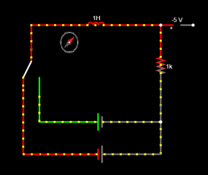
This week I personally worked on defining the Ampere-Maxwell Experiment that will be housed in our booth. I had an idea of what the experiment required: a solenoid with current flowing through it and a way to depict the magnetic field produced. I did some research and read about how the first time a magnetic field was observed from a current was when a compass was coincidentally placed near the wire. I decided to incorporate this fact in the experiment and then had to figure out how to alternate the polarity of the voltage source. This lead me to reading about Single Pull Double Throw (SPDT) switches that could alternate the connection of the solenoid between two oppositely oriented batteries. I designed the Circuit Schematic on an Online simulator, as shown below.
For this section of the work, I relied on my knowledge from the following ECE Courses: 18-220 (in making Circuits and simulating them) and 18-300 (to understand the Electromagnetic theory behind the Ampere Maxwell Experiment).


As for the blocker from the previous week (bridging the experiment hardware to our web app software), I researched on voltmeters that could direct our variables to a MySQL server that could be accessed by the web app. I decided to streamline the two experiments by using voltmeter readings in both to affect the animation in our web app.
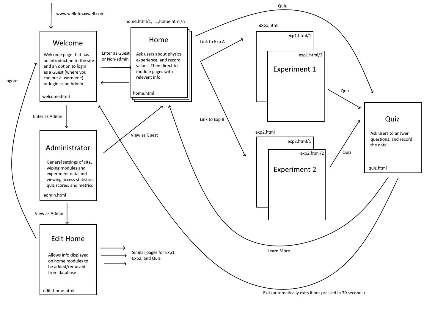
Furthermore, I worked on parts of the design review presentation, specifically in designing the Testing and Validation requirements, the Ampere-Maxwell schematic and the Gantt Chart for the project management section.
I believe my progress is good, according to the schedule we have in our Gantt Chart. In the Next week, I plan to start building a mock up of the Ampere Maxwell Experiment with the components I already have, and start putting in orders for the other circuit components I will require (SPDT switches, Compass, etc.).


