- Risks
- The biggest remaining hardware risk is that the FTDI circuit is incorrect. If it is, we will be unable to communicate with the FPGA board through it, and we will not be able to draw 9V from the USB connection. Our mitigation plan for this was to model the circuit as much as possible on a manufacturer created reference design, and to ensure we will be able to make the project even if it fails. This will be done by communicating with the FPGA board through its native USB or through an external UART-USB adapter, and powering our board with a 9V power supply connected separately. This will allow the project to function even if the USB plan does not work.
- Design Changes
- The lasers have been shifted to both be powered off of 9V rather than IR being 5V for consistency and ease of debugging.
- We added a 3.3V LDO to our custom board powered directly from 9V rather than relying on the one on the FPGA board powered by 5V. This is because the FTDI chip requires a 3.3V power supply, and since USB defaults to 5V, the FPGA board will be supplied 5V minus the dropout voltage of our LDO, which is about 1. We cannot guarantee that we will get the 3.3V back from that board that the FTDI chip needs in order to operate (and request 9V), so we need to have a way to get 3.3V reliable from the usb power regardless of voltage.
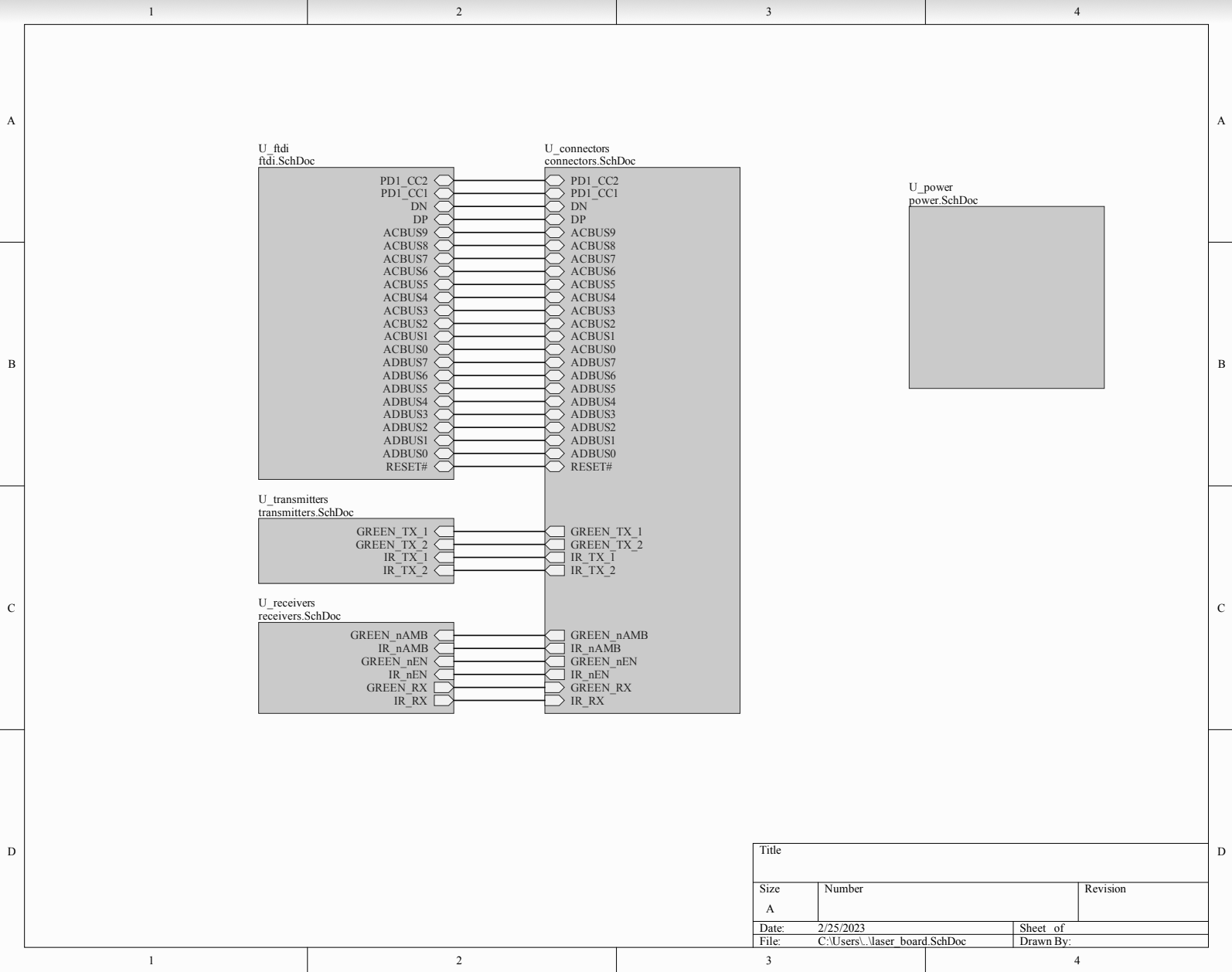
- We connected all interface pins from the FTDI chip to the FPGA GPIO so that we can decide to switch interfaces later, rather than being locked in to the one we pick before ordering the PCB.
- Updated Schedule
- We have no major schedule updates. We were able to test our lenses ahead of time, so no longer need to do that next week.
- Progress
- Our schematic is complete! Full schematic is located here and is 6 pages.. Below is the front sheet showing interfaces between different subsystems.
- The laser beam focus was one of our concerns, as we tested the beams last week and it was very wide angle. We tested out the laser again this week using empty laser housing that we ordered, and the beam was focused very well.
- Before:

- After:
- Before:
- Our schematic is complete! Full schematic is located here and is 6 pages.. Below is the front sheet showing interfaces between different subsystems.
- Team Dynamics
- There hasn’t been team issues working on our project.
- We have shifted some assignments so that each person has work to do. Initially, we weren’t sure if we would have signals aspects in our projects, because we considered the use of DSP to clean out the signals that we get. However, because we realized that there were complications using the ADC (sample rate), etc. we have decided to use comparators instead. If we were to implement this, Roger would have dealt with the signals. Instead, we moved some of the EEPROM configuration to his task. In addition, due to communication protocol difficulties that we might face, we also shifted the Hamming encoding/decoding to him as well.
- There was also a need for 3D printing that didn’t occur to us in the beginning. This has been taken on by KJ, since it would probably be easiest for him to interface with the PCB, and there will be more software/programming implementation for the rest of the team later on.
Anju Ito, Roger Lacson, and KJ Newman