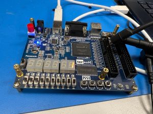
Tested speed of FPGA I/O pins from the Dev board to see how fast communication can go from custom PCB to the FPGA
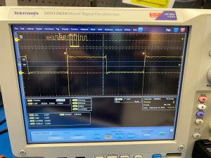
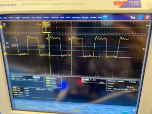
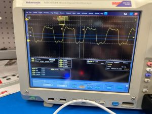
Measured that 12.5MHz clock can cleanly be measured from the GPIO pins. From this, we decided that using an FPGA dev board was sufficient and a better option than a microcontroller. Faster speeds yielded questionable results, although there is a possibility that the oscilloscope probes couldn’t measure as fast. We can safely rely on using the 12.5MHz clock (i.e. 25 Mbps) communication for our project.
FPGA Spec
50MHz clock
3.3V active high from GPIO pins
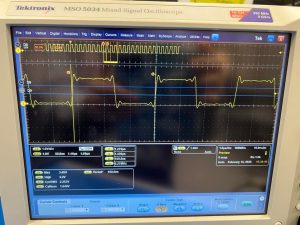
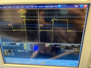
Detailed measurements:
4.15MHz from FPGA, measured with an oscilloscope at 500MS/s sampling:
Worked with Roger and KJ to come up with communication protocol.
We weighed the different options between a SPI-based and a UART-based protocol, and concluded that we will use a UART-based protocol for LaserDrop, as this would yield better results after evaluating it while thinking about sampling speed from FPGA, circuit response, etc.
Decided on the packet properties of the laser communication (start sequence, packet ID, data, Hamming encoding, packet size)
Decided which aspects of our project (CPU, FPGA, circuits, COTS IC) would handle which part of the protocol
Came up with an error handling mechanism for lost packets
Came up with a handshaking mechanism for beginning/end of instantiating a communication
Designed the FPGA block diagram that would handle this communication.
Overall FSM and block diagram that will interface with the FTDI chip and PCB circuitry.
Worked on the design review presentation with the whole group.
Schedule
My work is on schedule. My goal last week was to test whether the FPGA dev board or the microcontroller would be able to support the communication, which I was able to do. Due to the success of how fast the signals came across from the FPGA board, we concluded that a microcontroller would be unnecessary and we can go forth with a custom PCB that would interface with the FPGA.
Goal for next week
Practice and present the design review during class.
Address the feedback/concerns that we receive during the design review from the advisors, faculty, and classmates
Refine and come up with a detailed FSM/block diagram of the whole system
Principles/Courses Used
18-240, 18-341: In these classes, I learned how to use and design the FPGA boards (Altera DE0-CV), which I used to think about how the FPGA will interface with the FTDI chip and PCB circuits and handle the protocol that we designed. In addition, protocols such as the Hamming encoding and USB were explored in these classes that helped when we were coming up with the communication protocol. In addition, I wrote simple SystemVerilog code to test out the FPGA speeds, which I will heavily use later on in this project as well.
18-349: Embedded Systems taught about various protocols such as SPI, UART, and I2C that we thought through while coming up with our custom protocol. In addition, 18-100 and Manchester encoding, etc. were another features that we thought about when thinking about the communication protcol.
MoonRanger (16-861/16-865: Space Robotics): Gave me hands-on experience with communication protocols (UART, etc.) that helped during protocol design. In addition, I learned and often used oscilloscopes and other tools, which made it easy for me to figure out the FPGA speeds.