
This week, I finalized the PCB’s (should come late next week or early the week after). Turns out I was generating gerber files that did not include actual drill holes… I also removed parts that were not available in the board house with two through holes, so we can hand solder the missing parts. We may need to buy a 0.1uF capacitor and solder that on, which shouldn’t be too bad. I’m a bit scared that the support components PCB will end up not working on the first try, but we can always iterate.
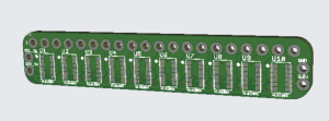
Sensor array PCB rev. 001
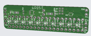
“Support” PCB rev. 001
I also bought some VL6180X sensor breakout boards from Amazon. These boards are the boards I based my PCB design off of. I played around with the sensors in Arduino with a Particle Photon as a preliminary test. I couldn’t get the IDE to recognize my ESP32. The Photon has WiFi capabilities, but not BLE, but that is probably ok. The sensors seem to be fairly sensitive and have a good range. Each sensor maybe has a ~1-2mm margin of error in relation to the other sensors, which isn’t too bad. I tested this by placing a piece of paper in front of three sensors hooked up to my Photon and recorded the readings. I implemented sensor reading in a round robin fashion due to IR interference, since each sensor records readings within a 25º (+/- 5°) cone (according to datasheet) and other sensors can interfere when one sensors is reading. I also added a small averaging filter to the readings.
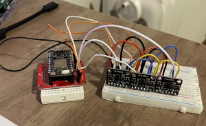
Sensor testbed
I am on schedule for this week and will work on communication stuff next week with the rest of the team.