
In order for our idea to work, we need an array of distance sensors. We need those sensors to be tightly packed and there does not exist an off the self solution for that. So, we decided to make our own custom PCB breakout board. We decided on the VL6180X proximity sensor by STM, since it can sense up to 5mm to ~150mm, which is about right for the length of a typical forearm. So, I sought out to make a PCB containing an array of these sensors. I built our PCB design off of this, since it provided an open source Eagle schematic. I figured building off an existing, working design will hopefully ensure that our design will be functional and make it so that we will have to iterate less.
So, this week, I worked on finalizing the first iteration of our PCBs on Eagle. I realized we needed to make two PCBs since I could not fit all of the SMT components unto a single one without making it too large. So, we will have two PCBs on our wearable device: one containing an array of VL6180X sensors and another containing all the “support” components like voltage regulators, resistors, etc.
I prepared them to order on JLCPCB and generated the BOM and CPL files that were needed. I will need to talk to a TA or a professor to verify that my design will work.
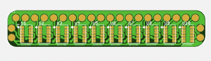
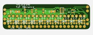
Sensor Array PCB
“Support Components” PCB
I also helped lasercut a rough prototype of our hologram pyramid with Anushka and Joanne.