Ji’s Status Report, Feb 19th

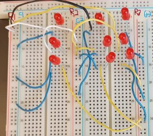
We’re currently in the Design Review stage, and we currently don’t have many parts for prototyping. So we’re making do with components scavenged from the lab.

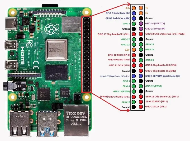
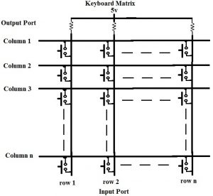
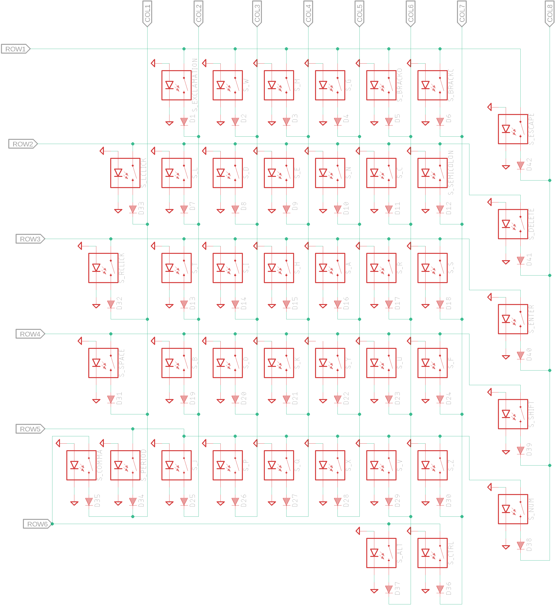
The circuit above is meant to simulate the circuit below; it is the matrix used for the keyboard. The purpose of the circuit is to test if the Raspberry Pi can detect if a switch is open (or closed), and if so, which row and column. That is, the circuit itself can’t do that; it’s a problem for the software to handle.

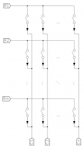
The blue wires are ‘real’ wires, while the other colors are pseudo-switches. The point of this circuit is to check if the Raspberry Pi could detect changes in switches, so you can pull (and replace) the non-blue wires to simulate a switch opening or closing.

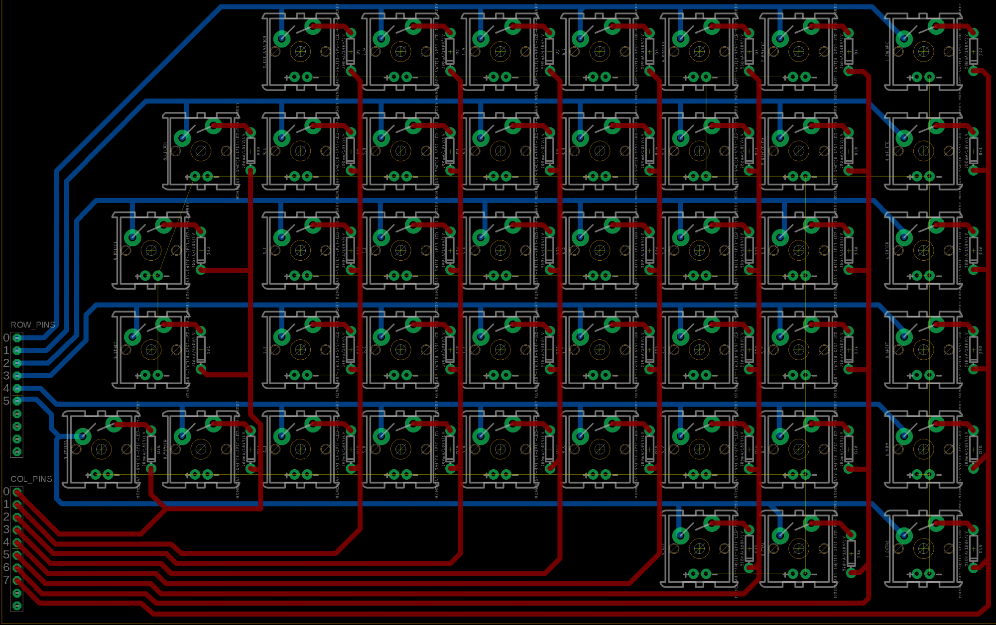
This may violate some rule, but R1, R2, R3, etc. are the Vcc columns, and C1, C2, and C3 are the Gnd columns. Real Vcc and Gnd can connect elsewhere.

In other words, all LEDs on the top row connect to R1, or the leftmost Vcc. All LEDs in the middle row connect to R2, or the center Vcc. All LEDs on the left column connect to C1, or the leftmost Gnd. It may be hard to see, but they’re labelled.

We couldn’t test it this week because we need a part to connect the Raspberry Pi to the breadboard.

Next week, we can look at the mouse.

Carlos’s Status Report for Feb. 19

This week I worked with my teammates to finish the design review presentation. I also started some testing with the Raspberry Pi to learn how to read and write to the GPIO pins. The gpiozero library that comes standard with Raspberry Pi OS provides all the functionality that will be needed for this. The following test script I made using Python was able to detect when pin 2 and ground were connected via a wire:

This means that the code for detecting whether or not a switch is pressed will be relatively simple once we have decided on a layout.

On the other hand, sending key inputs to a computer will be a bit more involved. According to this  link , it appears that there is a gadget system in place on Linux that has the desired functionality.

Since we didn’t schedule the software to be started until after the design report was due, I am technically working ahead of schedule. The meeting we have scheduled with Professor Carrington isn’t until next week, so we are limited in certain areas that we can start working on. The software for communicating signals is independent of the feedback we will receive from that meeting, so I started work on it sooner.

For next week, I plan to write a preliminary script to handle matrix scanning from the GPIO pins. I also hope to nail down exactly what the process of sending key presses to a host computer will look like.

Team Status Report for 2/19/22

This week we worked on the design review as well as got a lot of work done on the software and hardware side of things. We are trying to stay flexible since we know a lot of the hardware may change based on the feedback we receive, but generally we have a good go ahead to work on the software.

We created a survey that we may want to change later on, but it gives us a more quantitative way to measure comfort and ease of use. We also have a preliminary schematic for our board, but we know it is very likely to change after our feedback. There are also other potential changes to wire routing that may make it easier on the software side of things.

Here below is linked the Survey we made, which is also likely to change based on our feedback, but it gives us a good idea of how were going to measure quantitatively.

Preliminary Survey

In terms of schedule, we are ahead on the hardware side of things. This is mainly to make it easier once we get feedback to change our design quickly if needed. Since we cant get feedback until after the design review from the Professor in HCI, we need to stay flexible and be willing to change things, so being comfortable with Eagle well beforehand is very useful. On the Software side of things we are also on schedule.

Jorge’s Status Report for Feb. 19

  • Jorge’s Status Report for 2/19/22

This week we worked on the design review presentation, while also working on our project so we had some more solid metrics for the presentation itself.

We created a preliminary Survey together, with two different texts, each with a different level of difficulty, which people who test our keyboard will be asked to type. From these texts we will measure the errors through either software or visible observation. Beyond that, the survey also has some questions regarding the comfort of the device and some other metrics. This will hopefully give us more solid ground for our testing process.

In terms of work outside of the design review. I started working on the Eagle Schematic for the layout of our board.  The PCB itself however, will likely change once we get feedback on the design review and after. This along with some of the other things my teammates have done means that we are actually somewhat ahead of schedule, but in truth this is necessary since some of our work is subject to revision once we get feedback from the Professor in HCI who specializes on accessibility.


Above is the circuit schematic. Generally the layout is solid, but the special characters like Alt, Ctrl and Shift are likely to change to allow us to make the software simpler. Besides that, all thats left is a component so that when we go to make the board layout we have some location for male connector pins.

As stated before, we are somewhat ahead of schedule when it comes to some concrete work, but that basically means we are on schedule, since our chance to speak with a professor in HCI was only available after the design review.


Ji Chang’s Status Report, Feb 12th, 2022

On Monday, we looked at keyboard circuits. Basically, how does the Raspberry Pi detect each key when you press it?

The one my teammates proposed was a matrix keyboard, and I proposed a series of cascading resistors.

With a cascade resistor keyboard, each key in a row is mapped to a resistor switch, doubling each time. For example, the leftmost might have 100 ohms, the second on the left has 200, then 400, etc. so that the voltage difference across the row would change every time a key is pressed. The keys have different resistances so that the Pi can detect multiple key presses simultaneously and interpret the analog voltage drop as a binary bitvector.

Or at least, that’s what I remember. This is a digital to analog converter from Microelectronic Circuits, which does what I wanted. Every combination of digital inputs will change the voltage in a discretely unique way, which can then be interpreted on the Pi as a digital signal via an analog to digital converter.

This seems to work, but we haven’t seen this work in other keyboards, so we’re going with the matrix keyboard. I’ll leave this here as a backup.

To see how a matrix keyboard works, see the team status report.

I researched matrix layouts to see if I could build them, and I can say with several degrees of confidence that I can.

Carlos’s Status Report for Feb. 12

  • Carlos’s Status Report for 2/12/22

This week I picked up the Raspberry Pi that we will be using to emulate sending keystrokes to a host computer. I also started looking at how we might use it to send keystrokes to a host computer.  It seems like there are already some libraries that perform this task, so it may be worth looking into which ones will best serve our needs. Finally, I also scheduled a meeting for the team with Professor Patrick Carrington, an assistant professor in HCI who studies accessibility (among other things).

Jorge’s Status Report for Feb. 12

  • Jorge’s Status Report for 2/12/22

I started by designing some preliminary layouts for our keyboard which is designed for right handed use for now, but can be easily flipped if necessary. I based it off of existing layouts but with a goal to make a much simpler to use and intuitive layout. Besides the design of the keyboard button layout we also looked at the components we will be using. Standard mechanical keyboard switches work well and can be laid out in Eagle relatively easily.  We decided on linear key switches because they are the most comfortable to use and Carlos will be designing some custom keycaps for them that will be slightly bigger than standard.

For the board itself we will use a matrix scanning design to get the most use out of our IO pins on the Pi. Currently with only 26 GPIO pins it may be difficult to get 40+ keys to work but that becomes a non-issue when using matrix scanning. With Matrix scanning for every ‘n’ pins we get ((n^2)/4) possible input combinations which means we have more than enough input.


Team Status Report for 2/11/22

We reached out to Professor Carrington in the HCI department for advice on designing with accessibility in mind as that is his specialty. We cant design assuming that we know everything going into it and the only time available to speak with the professor was after the design review so we scheduled it then. In the meanwhile, we designed a preliminary  layout for the board that we think works well, which is based on existing one-handed keyboards.

On the technical side of things we decided on a few components that we are going to use. We’re using standard mechanical keyboard switches which will have custom caps designed and 3d printed. They will be slightly larger than normal to improve ease of use without being too bulky.

The Pi only has 26 GPIO pins but thats more than enough even for a 40+ key keyboard because we will be using matrix scanning to make the most use out of them. for every N input pins this gives us (N^2)/2 possible inputs, which is more than enough.

On the 

Matrix scanning works by taking in one row and one column of keys. Each key is connected to a switch (depicted as transistors), and when a key is pressed, it alters the voltage on the col pin, so it reads all the pins in the col. It then detects which pin by looking at which row. This efficiently reduces the time and number of pins, but only one key can be pressed at a time.