Jorge’s Status Report Apr. 16

This week I did not manage to get work done. I fell very ill with an infection and had to take antibiotics for fever, headache, and sore throat. This is not been the most productive week for the team as a whole as all of our members were sick, I with strep, my teammates with covid.

It is going to be hard going forward to see if we have enough time to implement a mouse idea which we have and could be better than our mouse option, but we have to wait until the team is back in one piece.

Team Status Report Apr. 9

We finally have a full board up and running and tested with our Pi. The only functionality we need to add is the ability to produce a mouse click with the keyboard. Currently we can do keyboard type inputs or Mouse type inputs but not both so we need to work on the software and switch between the two when necessary. Otherwise, the matrix scanning and the PCB as a whole is working great.


Carlos’s Status Report for Apr. 10th

This week I worked on implementing mouse clicks via a key press. The USB gadget system that Linux uses only allows one device to be simulated at a time. So, for this to work, the keyboard device needs to be “disconnected” and the mouse needs to be “connected” when performing a mouse press. I plan to fully implement this functionality next week. Also, we were able to run the breadboard software of a 2×2 grid on the PCB that was printed (connections shown below).

Ji Status Report April 9th

We worked on the mouse on Monday.

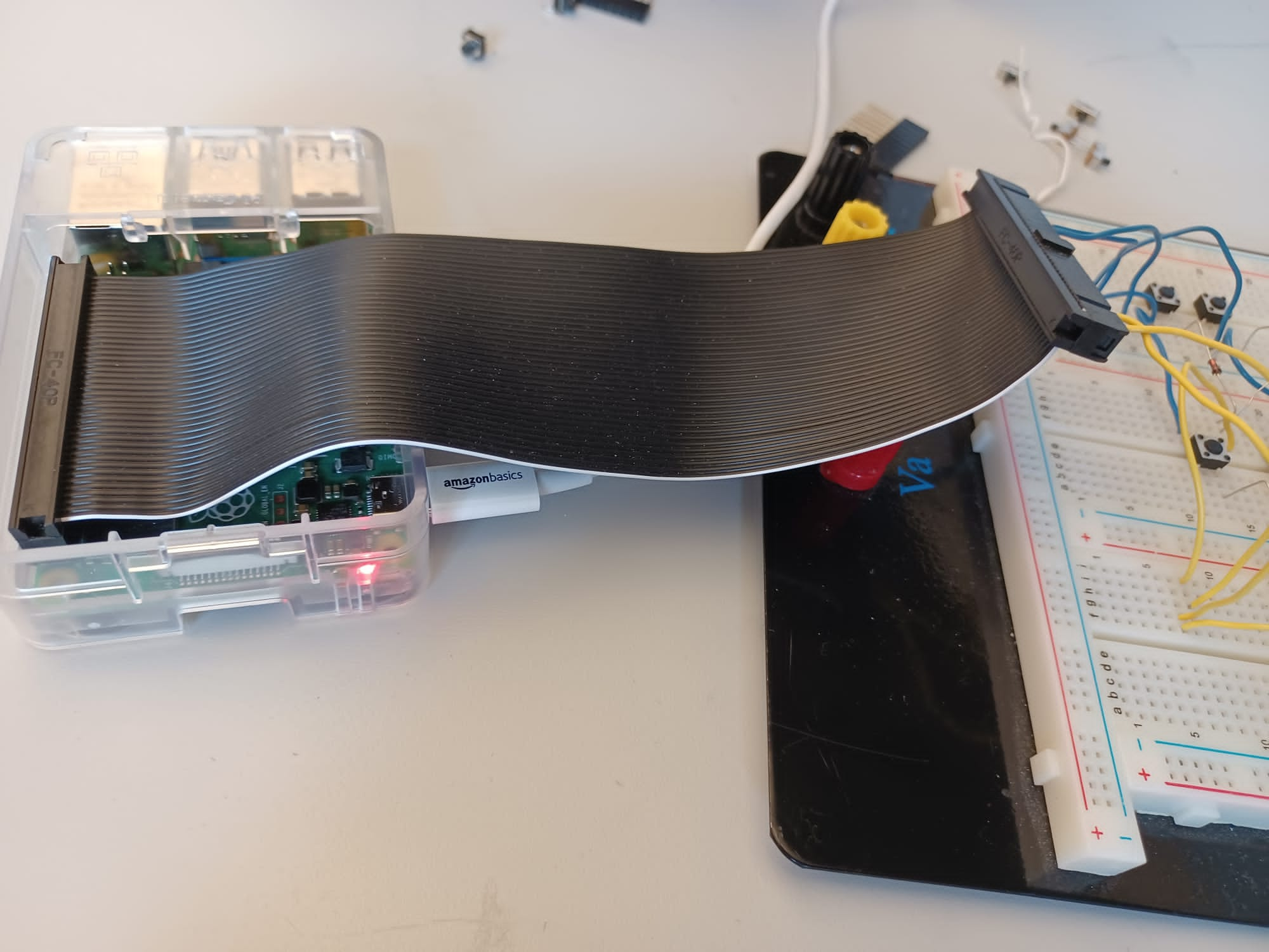
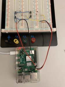
My teammates are working on getting the pi to approve a mouse click, and mouse motions.

We’re looking into taking apart a mouse and then making a new chassis. I’m looking into other ways to operate a mouse with your foot. Actually, we’re now looking into joysticks.

I tried using my computer touchpad with my foot. I could move it, but it didn’t respond well to upward motions and I had trouble with fine movements. Lifting my leg for a long period of time also tired me. So we’re not going to use a touchpad.

In general, mouse sensitivity would have to be reduced, since our feet aren’t as precise as our fingers. We should also include the option to have a normal, hand-operated mouse as a backup. I guess that’s more of a number of USB ports than anything else.

I now think that a joystick is the best way to operate a mouse with your foot. The circle pad on the 3DS looks like the best, since it slides and is concave, but we can’t get a larger version.

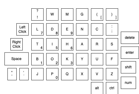
Since we already know how to make buttons, we could do a d-pad, with four buttons.

Dance Dance Revolution pad, if smaller.

Since reducing mouse sensitivity would make mouse movement slower, I had thought that holding the stick/key/pad/whatever would gradually speed things up. Then I remembered that hold key presses were the most common error, so we shouldn’t do that.

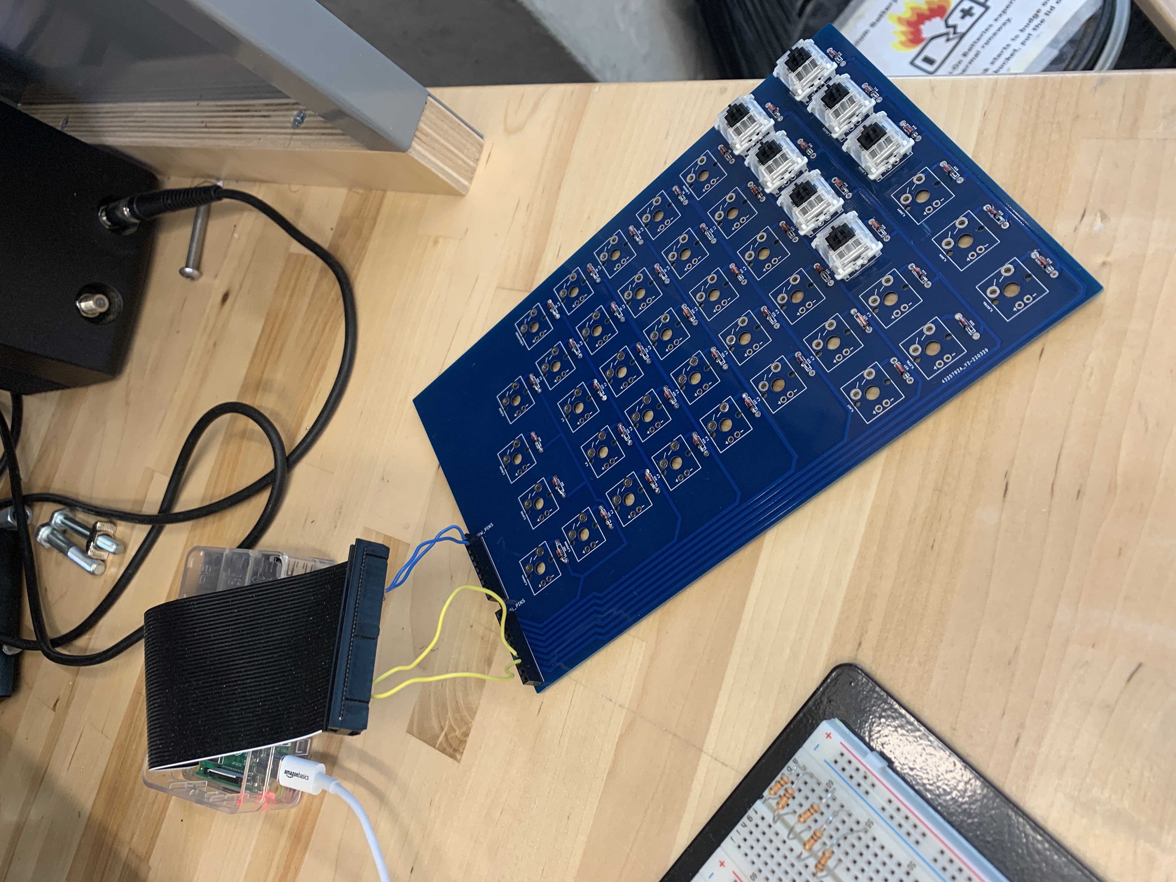
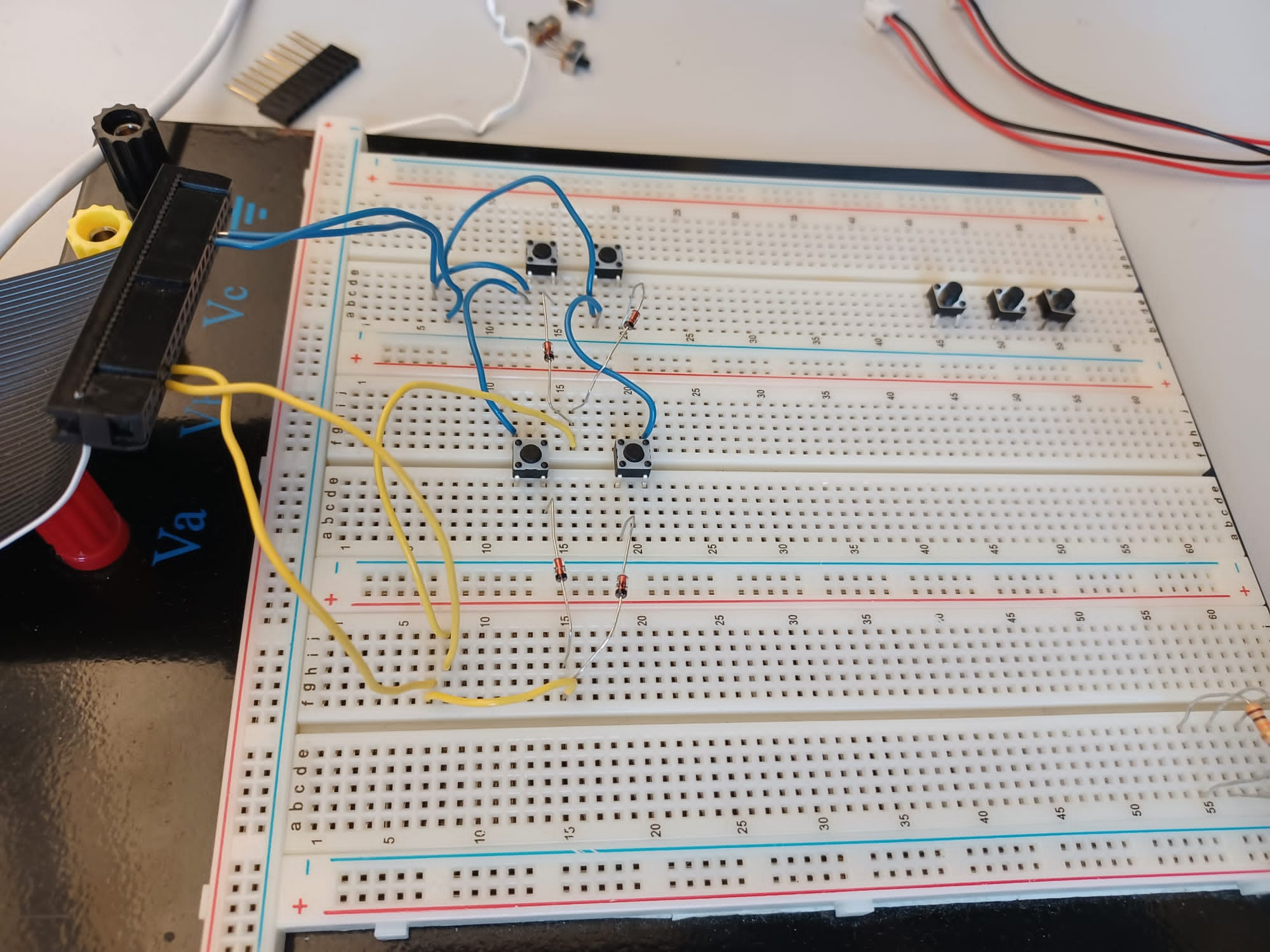
On Wednesday, Jorge and I soldered the diodes to the board.

Jorge’s Status Report Apr. 9

We finally got our PCBs this week so I took the time to solder on all the diodes and switches and put on some key caps. It was a little hard to keep the switches straight since the switches we ordered did not come with the two mounting holes for some reason, so the switches are not completely straight but thats okay since the key-guard will fix that issue somewhat. Regardless, if we need to populate another board that is also something that we can do since we have 5 of them.

I tested the board with Carlos and it all seemed to work perfectly. All that is left for the full functionality is on the software side.

Carlos’s Status Report Apr. 2nd

This week I modified the keyboard software so that it behaved like a standard keyboard. The reason it was sending thousands of key presses very quickly before was due to the way I was implementing the report descriptors. The way they work is that you send a list of keys pressed, and when a key is released, it is removed from the list that you send. So, now it only removed keys from the list if they are no longer pressed. One other thing to note is that the USB standard only allows up to six keys to be pressed simultaneously.

Ji Status Report April 2nd

This week, we discussed the mouse setup. We were primarily focusing on the keyboard, so we had neglected the mouse design. The mouse will be foot-operated, and the clicks will be on the keyboard.

I proposed looking at larger touchpad peripherals, and placing them on the floor. To ensure that only the more dexterous foot can interact with the keyboard, we proposed that the more functional foot is wearing a sock treated with the cloth that can be used on touchpads, and the other foot is wearing a normal sock. This might cause some problems in hot weather, though. The team accepted that this is a possibility, but we did not finalize the design.

This is the link to the trackpad. This is the largest one we could find, at 6*4 inches.

Once we get the PCB, I want to solder them.

Jorge’s Status Report Apr. 2

This I ordered the PCBs for our team after making some quick layout changes to make it easier to interface with the Pi.

Below is the board with the set of row pins routed underneath and the column pings routed on top. The extra pins are not necessary but I left them in, in case we wanted to add more buttons later on and I saw no harm in it. Right now, our layout hasn’t changed much from our older one, but there is a new button (very bottom right) to be used for the toggle repeat feature we intend to implement.

It is effectively a variation on thiss layout below, with the right most keys shifted up half a button length (10mm) and an added special button on the bottom right and an added button on the top right (an escape key we forgot to add earlier).

I ordered 5 of these boards as it was the minimum from JLCPCB, but they were fairly cheap, so if we need to order more I think it will be okay. The only issue is that if we do need to make changes to the layout I am worried about the time it will take to get the board shipped.


Team Status Report Apr. 2

This week we worked on the demo for the board. We wont be able to get out PCB in time for the demo so we will demo on our breadboarded circuit. Besides not having the PCB and keyboard switches we do currently have the correct diodes and the operation of the breadboard should be identical to what the PCB will do.

We worked on the software and made some tweaks so that it behaves like a typical keyboard and made sure that it worked with our application of choice (Minecraft). After some fiddling with keyboard protocols we managed to get it to behave exactly like a typical keyboard and function exactly like we wanted it to for the demo.

The operation of everything looks really promising and we basically just have to get our PCBs and switches to get the keyboard fully operational. We feel we have a decent chunk of the sub-system finished to show off at demo. From this point on, the difference from the demo board to the full PCB board should be mostly superficial so we feel confident we can get it all working as intended which gives us time to start working on our foot controlled mouse. For the demo, we will likely use a regular mouse in its place.


The following is our breadboarded circuit in operation. (This layout will be changed for the demo so that its more pleasant to operate) Just including it to show what a simple 2×2 matrix looks like on the breadboard and show we got it working. Scaling this up to more buttons is superficial at best so it should be no problem to get the entire board working once we get the PCBs.

We plan to have a layout for the demo that allows movement in Minecraft which only requires a few buttons on the breadboard (wasd).

Carlos’s Status Report for March 26

This week, the diodes we ordered arrived. I set up the circuit we had originally planned on to make sure that unique keys can be detected. The script I ran can be seen here. I modified the script to be easier to use different keys, and the only change that will need to be made is adding more IO pins to the row and column lists. I also made a class to keep track of what values correspond to what keys when sending the keyboard reports. These values are based on the documentation from the USB  usage tables. An image of the circuit I set up is shown below. The blue wires correspond to the rows, and the yellow wires correspond to columns. The circuit diagram can be seen in an older team post here.

When all four switches are closed, all four keys are detected, and every combination of on and off for each switch is recognized as distinct. This means the ghosting issues we were seeing before were caused due to the missing diodes, and that the diodes are not optional for functionality.

On another note, CLASS has not responded to my email yet, so I will need to look into following up and potentially using another source of contact.