Team Status Report April 30th

This week was a presentation week.

Ji drew the letters onto the keyboard. Since laser cutting might damage the keys or might otherwise be imprecise, we used a pen. To prevent the ink from rubbing off, we placed scotch tape over the keys as a temporary measure. This would especially be important because testers would have hand sanitizer.

Jorge tested the mouse, and suggested adding a block on the bottom to make it more comfortable. It otherwise worked.

Team Status Report Apr. 23

This week we worked on the final parts necessary to have a complete demo with fully functioning pieces. The only internal issue we have a is a delay occurring when switching from mouse to keyboard functions on the keyboard but we have a work around and are implementing that currently.


Besides that we have half the housing for the mouse finished, the top plate that straps to the show below. The mouse circuit we are using we already have and a backup as well, we have it tested and it works perfectly, we just need a 3D printed piece which will attach to the top plate in the image below.

The mouse we are implementing is the same as our original idea, which we felt we were more capable of finishing it on this tight time frame. All in all, we are on schedule to finish everything finally, although we had to work some extra hours to get the housing and things finished.


The keyboard housing has also been finished with a key-guard included. Currently the key-guard is not attached while we decide if we want it as an option or not, but attaching it is no issue if we wanted to.

Team Status Report April 16

This week all members of the team were sick; Jorge had strep throat, Carlos with Covid, and Ji with the flu. This has been a difficult week to for work, with our entire team being out of commission and no work getting done but hopefully we will recover promptly and make up for lost time next week.

Team Status Report Apr. 9

We finally have a full board up and running and tested with our Pi. The only functionality we need to add is the ability to produce a mouse click with the keyboard. Currently we can do keyboard type inputs or Mouse type inputs but not both so we need to work on the software and switch between the two when necessary. Otherwise, the matrix scanning and the PCB as a whole is working great.


Team Status Report Apr. 2

This week we worked on the demo for the board. We wont be able to get out PCB in time for the demo so we will demo on our breadboarded circuit. Besides not having the PCB and keyboard switches we do currently have the correct diodes and the operation of the breadboard should be identical to what the PCB will do.

We worked on the software and made some tweaks so that it behaves like a typical keyboard and made sure that it worked with our application of choice (Minecraft). After some fiddling with keyboard protocols we managed to get it to behave exactly like a typical keyboard and function exactly like we wanted it to for the demo.

The operation of everything looks really promising and we basically just have to get our PCBs and switches to get the keyboard fully operational. We feel we have a decent chunk of the sub-system finished to show off at demo. From this point on, the difference from the demo board to the full PCB board should be mostly superficial so we feel confident we can get it all working as intended which gives us time to start working on our foot controlled mouse. For the demo, we will likely use a regular mouse in its place.


The following is our breadboarded circuit in operation. (This layout will be changed for the demo so that its more pleasant to operate) Just including it to show what a simple 2×2 matrix looks like on the breadboard and show we got it working. Scaling this up to more buttons is superficial at best so it should be no problem to get the entire board working once we get the PCBs.

We plan to have a layout for the demo that allows movement in Minecraft which only requires a few buttons on the breadboard (wasd).

Team Status Report March. 26

This week we received our diodes and were able to set up a 2×2 prototype of our board. Ee will order the PCB from whichever board-house is most convenient and fast. Besides that, there didn’t seem to be any immediate issues with the PCB so ordering it after this point shouldn’t be too big of an issue.

We reached out to CLASS about finding someone with Cerebral Palsy but have yet to receive a response.

Progress was slow this week since we only really met on Monday because Tuesday was our Ethics Meeting. Progress should be back on track next week.

Team Status Report March 19th

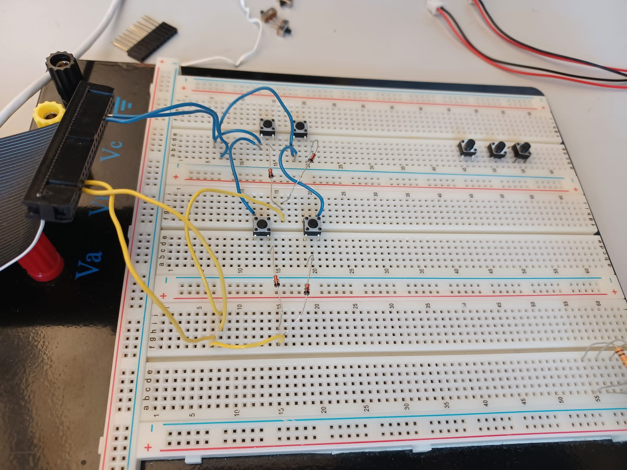
Before spring break, we tried making a better prototype. We did not fully understand how matrix scanning worked, so we assembled a new prototype. This did not work, and upon closer inspection we learned that our diodes were not the right type.

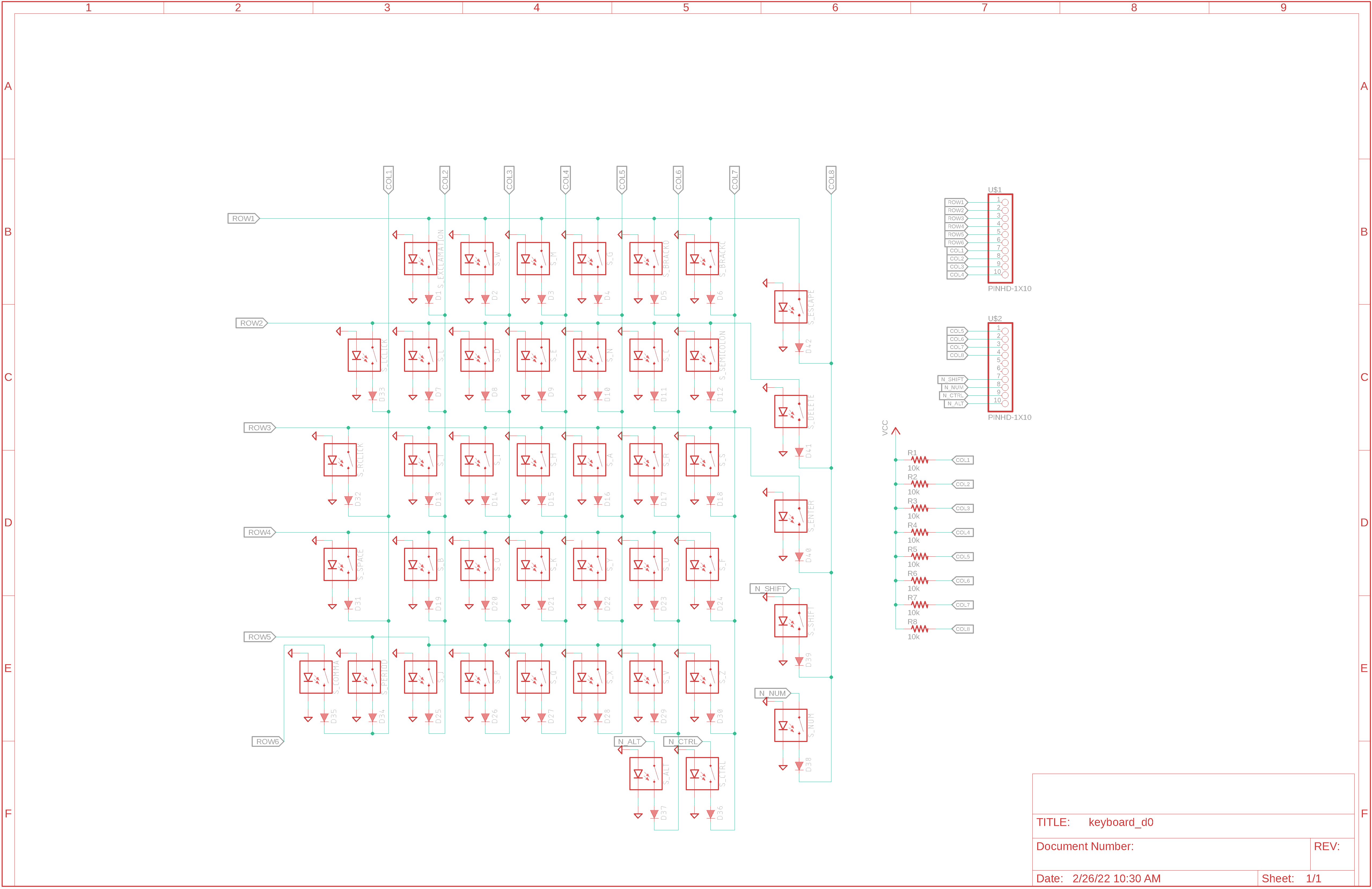
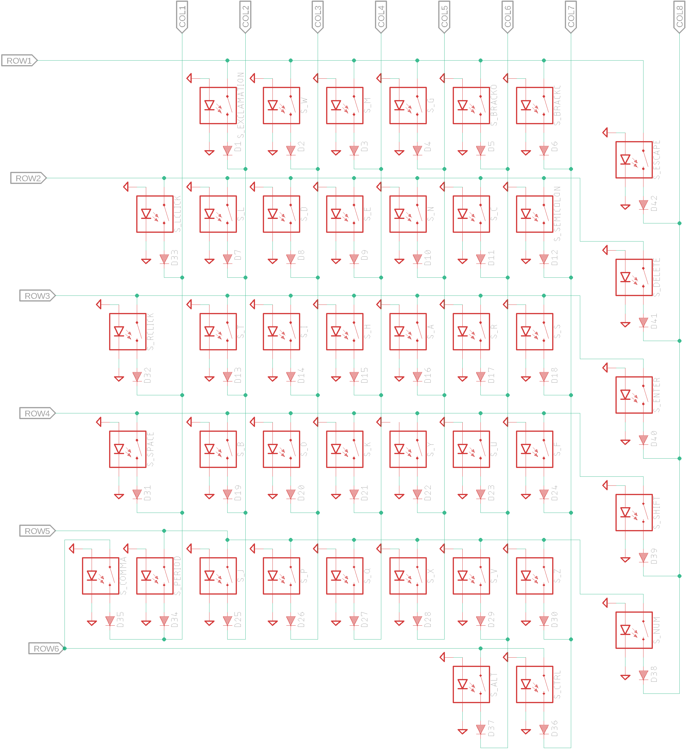
The scanning matrix works by quickly cycling through each column, such that the selected column is pulled to digital low and all other columns are at digital high. It then checks which rows have been pulled low from the switches.

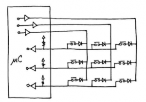
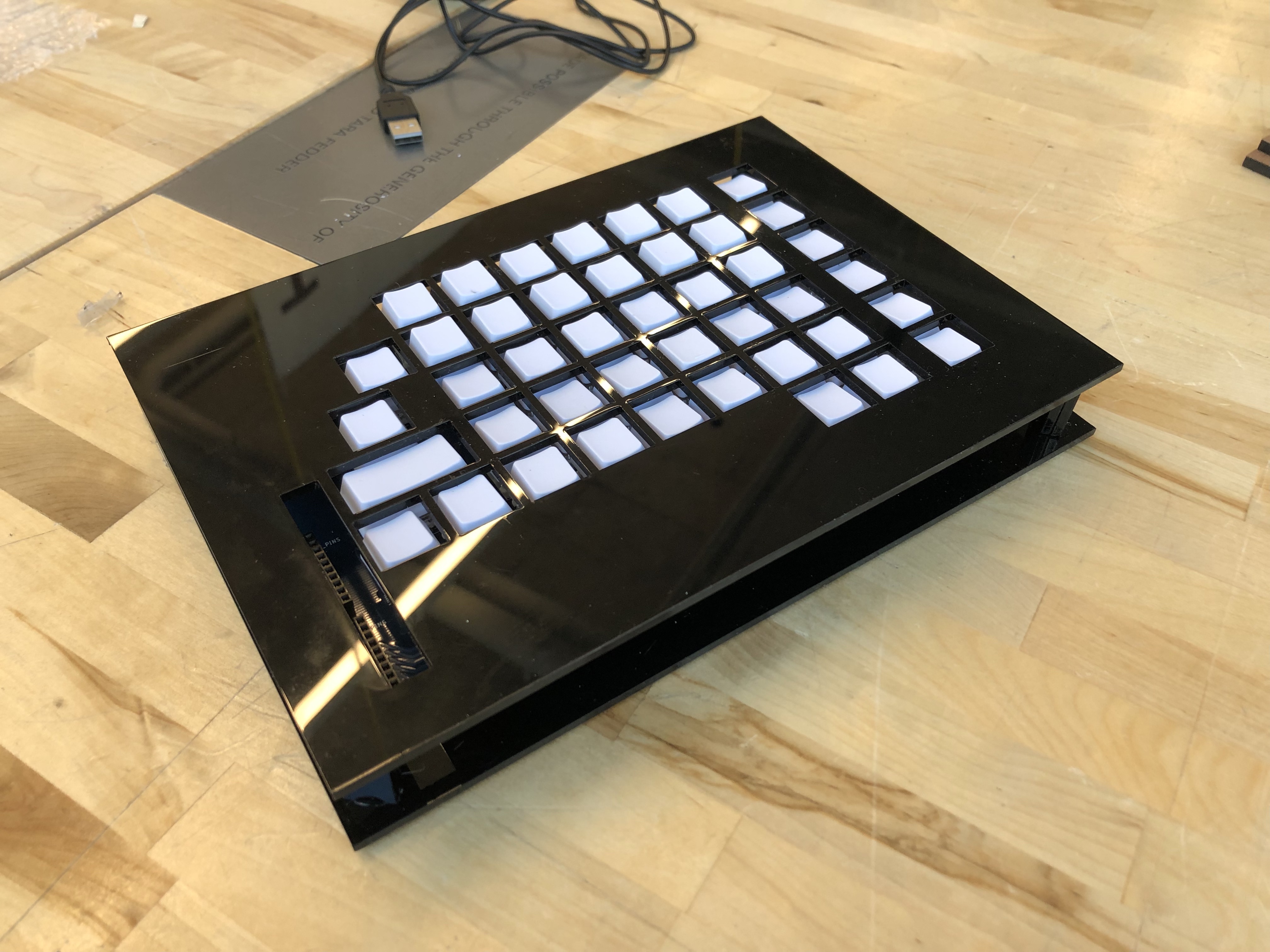
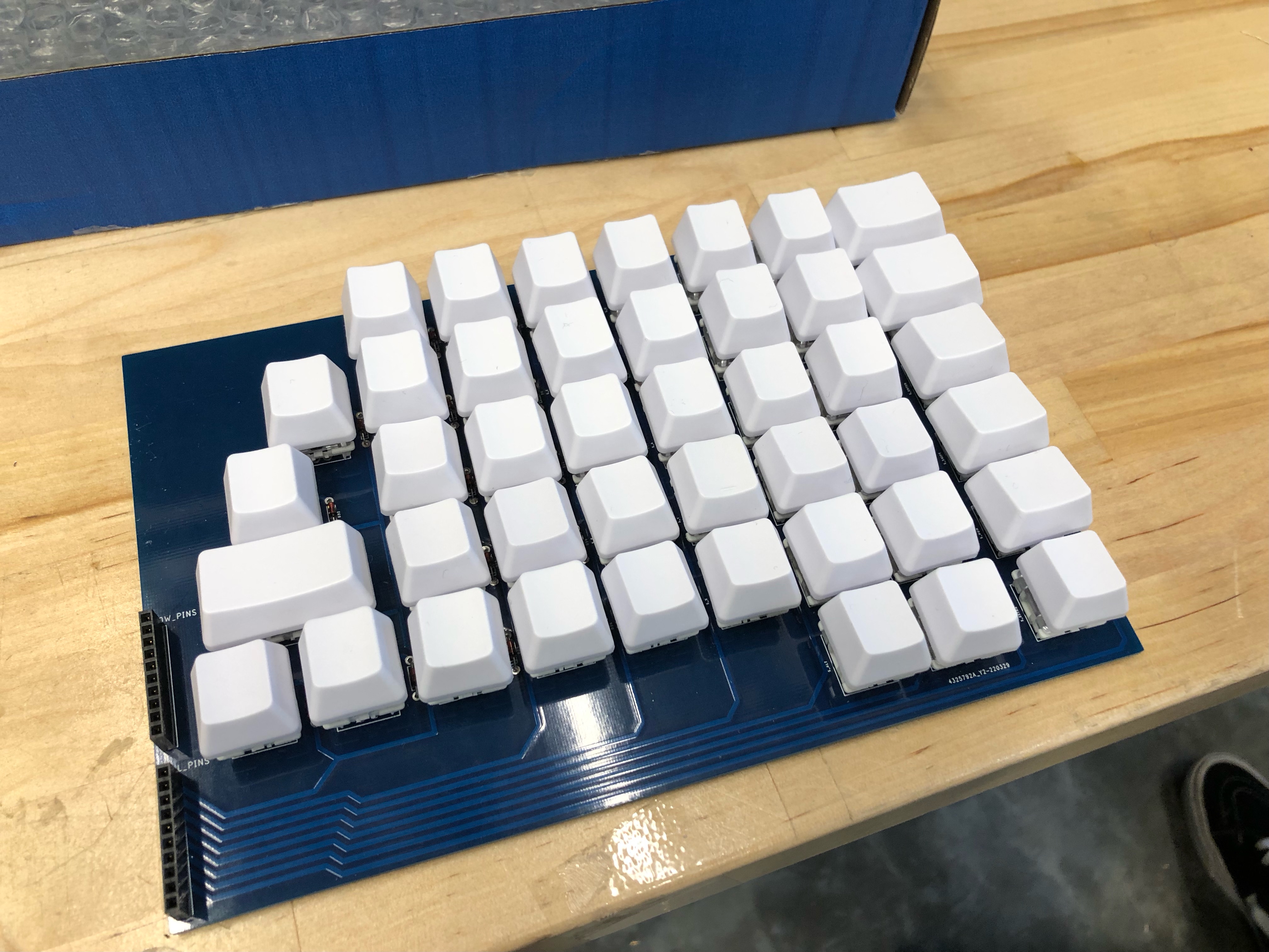
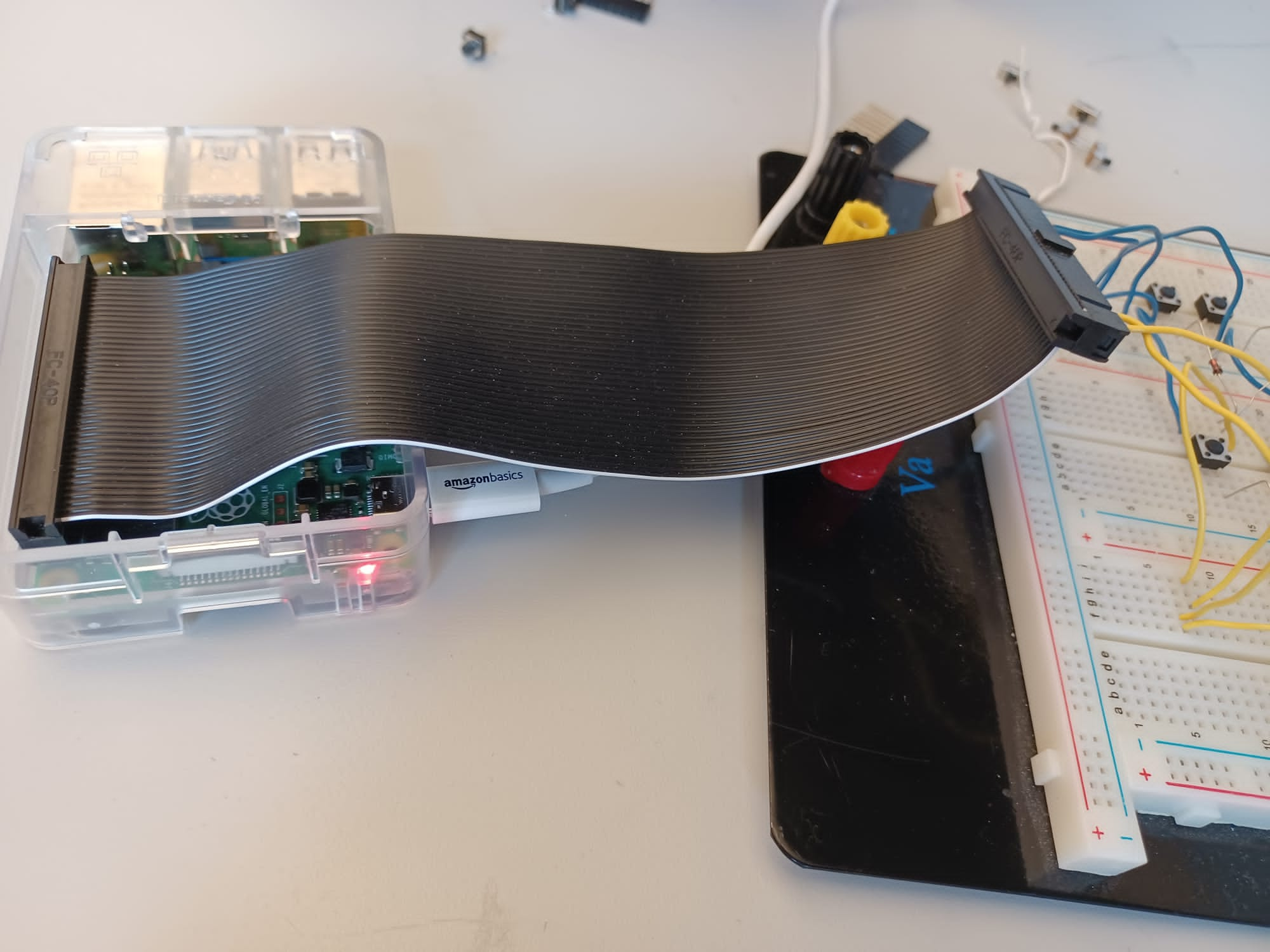
Here is a smaller scale version of the switch.

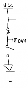
When we tried making the circuit, we failed because on closer inspection, we had the wrong kind of diode. We used LEDs, which on average drops 1.7 to 2 volts, which would mean that a row with a closed circuit would drop from 3.3 volts to 1.7 volts, which is still a digital high. We are now trying to find diodes with a lower voltage drop, around .3 volts, so that row can be pulled down to a voltage low. We have just ordered a new set of these diodes and are awaiting supplies.

We then moved on to testing the software without the diodes, which helped, but we had the expected ghosting issue. But since the ghosting only happened when multiple columns were on at a time, the circuit and software seems to work and should still work when we add the right diodes.

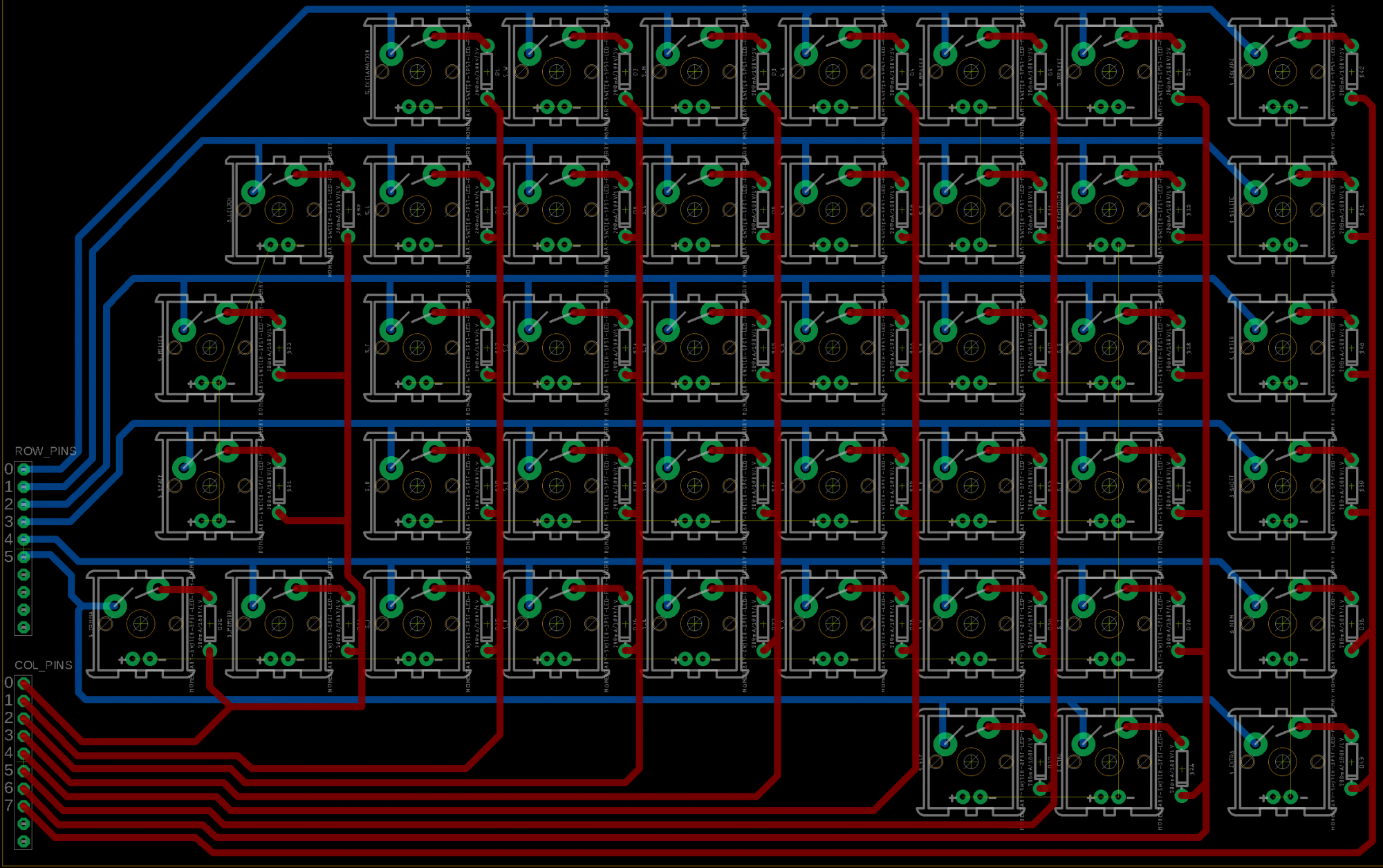
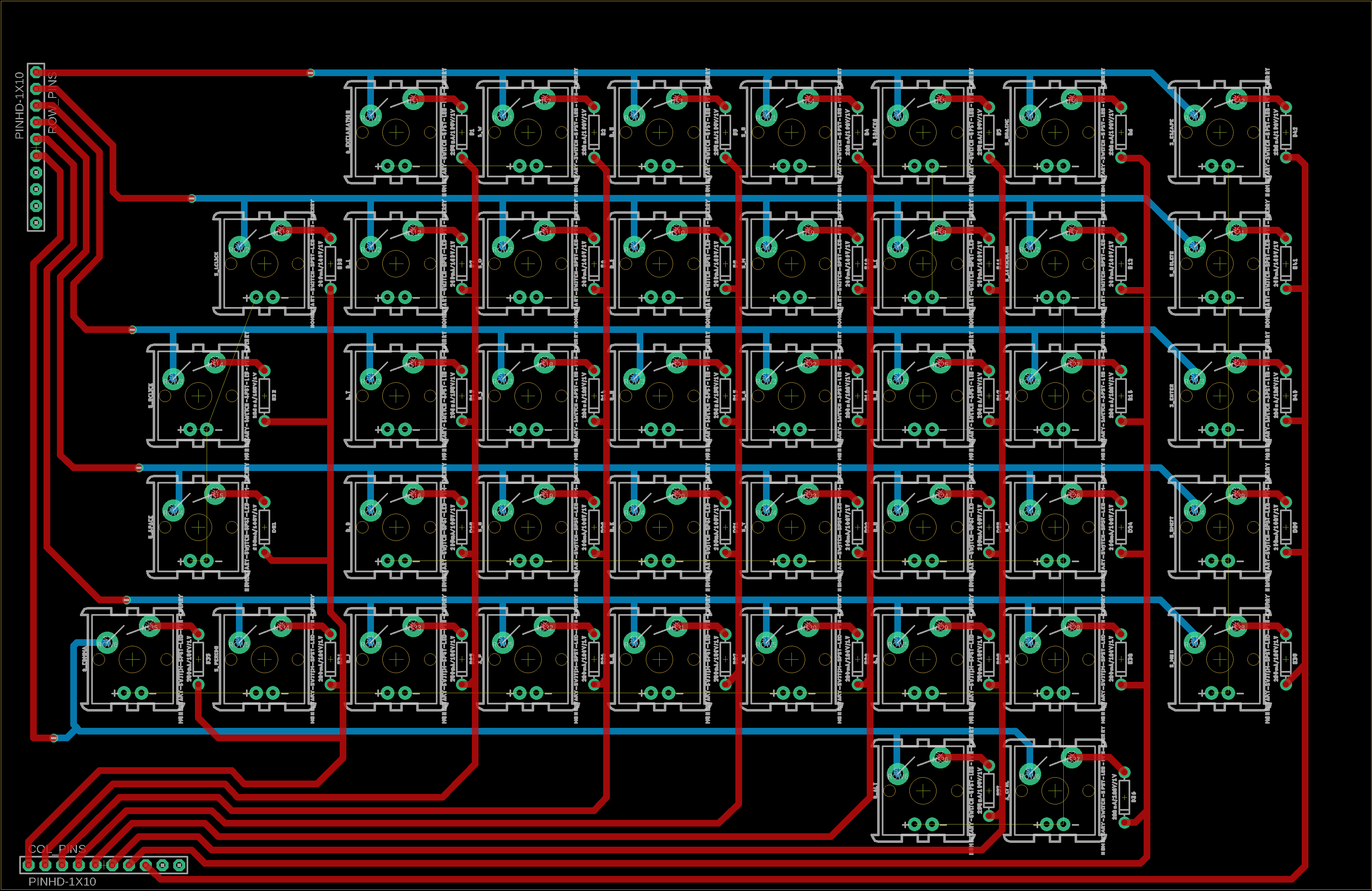
When it comes to making the PCB, we ran into issues because our board went over the maximum dimensions that Eagle free would allow, so we needed a proper Eagle education license. This was an annoying delay but I (Jorge) submitted my enrollment documentation and the license was supplied the next day. It was a minimal delay, and instead of getting the PCB design finished on Wednesday I got it done Friday. Next steps would be to revise it a little and then decide on a board manufacturer and order it some time next week.

Here below is the board PCB layout

[Note: More specifics on the design in Jorge’s personal status report]

Carlos is also going to reach out to CLASS this week. An organization which the professor in HCI recommended to put us in contact with someone with Spastic Hemiplegia.

Team Status Report for 2/26/22

This week, Jorge presented the design review for our team. Also, we started writing the report that goes along with it.

Jorge worked on modifications to our keyboard schematic.

Carlos managed to get the Pi to communicate keyboard inputs for the first time, which is a big step in our software implementation. We should follow this up by prototyping our keyboard on a breadboard and seeing if we can integrate our inputs with our outputs.

Our meeting with Professor Carrington was originally supposed to be on Friday, but was postponed to Monday.

Schedule:

In terms of schedule, we have made progress on all fronts, so we are on good pace. It would have been nice to have the meeting on Friday as originally planned but we have done well to compensate for any delays so far.

Team Status Report for 2/19/22

This week we worked on the design review as well as got a lot of work done on the software and hardware side of things. We are trying to stay flexible since we know a lot of the hardware may change based on the feedback we receive, but generally we have a good go ahead to work on the software.

We created a survey that we may want to change later on, but it gives us a more quantitative way to measure comfort and ease of use. We also have a preliminary schematic for our board, but we know it is very likely to change after our feedback. There are also other potential changes to wire routing that may make it easier on the software side of things.

Here below is linked the Survey we made, which is also likely to change based on our feedback, but it gives us a good idea of how were going to measure quantitatively.

Preliminary Survey

In terms of schedule, we are ahead on the hardware side of things. This is mainly to make it easier once we get feedback to change our design quickly if needed. Since we cant get feedback until after the design review from the Professor in HCI, we need to stay flexible and be willing to change things, so being comfortable with Eagle well beforehand is very useful. On the Software side of things we are also on schedule.

Ji Chang’s Status Report, Feb 12th, 2022

On Monday, we looked at keyboard circuits. Basically, how does the Raspberry Pi detect each key when you press it?

The one my teammates proposed was a matrix keyboard, and I proposed a series of cascading resistors.

With a cascade resistor keyboard, each key in a row is mapped to a resistor switch, doubling each time. For example, the leftmost might have 100 ohms, the second on the left has 200, then 400, etc. so that the voltage difference across the row would change every time a key is pressed. The keys have different resistances so that the Pi can detect multiple key presses simultaneously and interpret the analog voltage drop as a binary bitvector.

Or at least, that’s what I remember. This is a digital to analog converter from Microelectronic Circuits, which does what I wanted. Every combination of digital inputs will change the voltage in a discretely unique way, which can then be interpreted on the Pi as a digital signal via an analog to digital converter.

This seems to work, but we haven’t seen this work in other keyboards, so we’re going with the matrix keyboard. I’ll leave this here as a backup.

To see how a matrix keyboard works, see the team status report.

I researched matrix layouts to see if I could build them, and I can say with several degrees of confidence that I can.