Ji’s Status Report, Feb 19th

We’re currently in the Design Review stage, and we currently don’t have many parts for prototyping. So we’re making do with components scavenged from the lab.
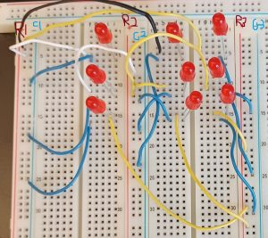
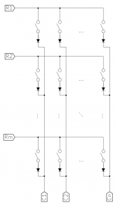
The circuit above is meant to simulate the circuit below; it is the matrix used for the keyboard. The purpose of the circuit is to test if the Raspberry Pi can detect if a switch is open (or closed), and if so, which row and column. That is, the circuit itself can’t do that; it’s a problem for the software to handle.
The blue wires are ‘real’ wires, while the other colors are pseudo-switches. The point of this circuit is to check if the Raspberry Pi could detect changes in switches, so you can pull (and replace) the non-blue wires to simulate a switch opening or closing.

This may violate some rule, but R1, R2, R3, etc. are the Vcc columns, and C1, C2, and C3 are the Gnd columns. Real Vcc and Gnd can connect elsewhere.

In other words, all LEDs on the top row connect to R1, or the leftmost Vcc. All LEDs in the middle row connect to R2, or the center Vcc. All LEDs on the left column connect to C1, or the leftmost Gnd. It may be hard to see, but they’re labelled.

We couldn’t test it this week because we need a part to connect the Raspberry Pi to the breadboard.

Next week, we can look at the mouse.
Ji Chang’s Status Report, Feb 12th, 2022

On Monday, we looked at keyboard circuits. Basically, how does the Raspberry Pi detect each key when you press it?

The one my teammates proposed was a matrix keyboard, and I proposed a series of cascading resistors.

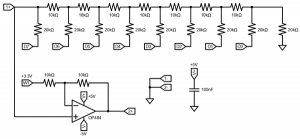
With a cascade resistor keyboard, each key in a row is mapped to a resistor switch, doubling each time. For example, the leftmost might have 100 ohms, the second on the left has 200, then 400, etc. so that the voltage difference across the row would change every time a key is pressed. The keys have different resistances so that the Pi can detect multiple key presses simultaneously and interpret the analog voltage drop as a binary bitvector.

Or at least, that’s what I remember. This is a digital to analog converter from Microelectronic Circuits, which does what I wanted. Every combination of digital inputs will change the voltage in a discretely unique way, which can then be interpreted on the Pi as a digital signal via an analog to digital converter.

This seems to work, but we haven’t seen this work in other keyboards, so we’re going with the matrix keyboard. I’ll leave this here as a backup.

To see how a matrix keyboard works, see the team status report.

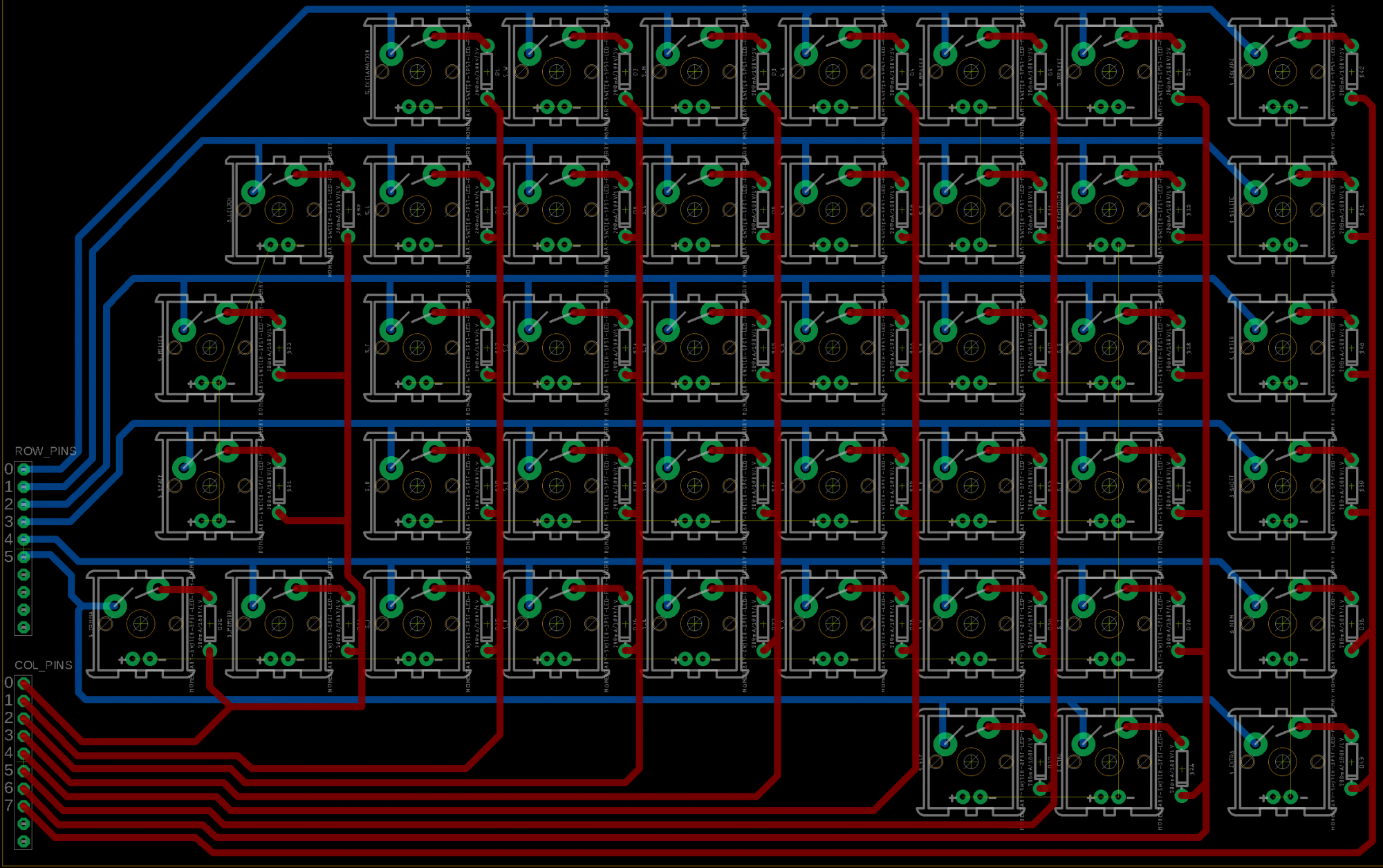
I researched matrix layouts to see if I could build them, and I can say with several degrees of confidence that I can.