Kelton’s Status Report 04/30/2022

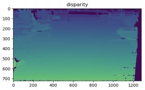
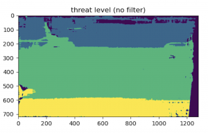
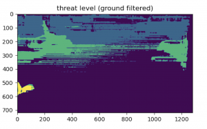
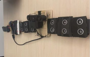
This week I finalized the depth imaging model with Ning as detailed in the team status report. And then I tested the integrated sensor feedback model with Ning and Xiaoran. Through this testing, we first, discovered and fixed latency issues between ultrasonic sensing and vibrational feedback; second, changed the number of threat levels from three to two to make the vibration difference more distinguishable; third, made communication between Raspberry Pi and Arduino more robust by explicitly checking for milestones like “sensors are activated” in our messaging interface instead of relying on hand-wavy estimates of execution times.

I also tried two different ways of launching the raspberry pi main script at boot up, i.e., @reboot with cron job scheduling and running in the system admin script rc.local , without success. Upon boot up, while the process of the script can be seen, the physical system is not activated. Now the system can be demoed by running remotely through SSH, but I will troubleshoot this further during the week. Between now and demo day, I will also further test, optimize, and present the system with the team.

Team Status Report 04/30/2022

This week, we are mostly testing and optimizing based on the tests.

For depth image modeling, we visually examined the threat levels generated from the stereo frame of the depth camera. The disparity frame below is calculated at room HH1307.

But the threat level from our model shows that ground is not recognized as a whole due to perceived depth based on depth camera’s downward orientation.

With the addition of a filter based on a height threshold, we are able to achieve the effect of ground segmentation and thus more realistic threat level as shown below (the deeper the color the smaller the threat).

Beside tests revolving around accuracies such as the one above, we also looked into latency across every stage of the sensing and feedback loop. To make sure data sensed by depth camera and ultrasonic sensors model the same time instance, data rate from Arduino to Raspberry Pi is tuned down to match the depth camera.

During user testing, we found it hard to tell the three vibration levels apart and thus changed the number of threat levels from three to two to make the vibration difference more distinguishable.

We also made communication between Raspberry Pi and Arduino more robust by explicitly checking for milestones like “sensors are activated” in our messaging interface instead of relying on hand-wavy estimates of execution times. This marked the 49th commit in our GitHub repository. Looking at the code frequency analysis of our repo, it can also be seen 100+ additions / deletions are made every week throughout the semester as we iterate in terms data communication, depth modeling, etc.

Meanwhile, the physical assembly of electronic components onto the belt is completed as two batteries, the Raspberry Pi and Arduino board have been attached besides just ultrasonic sensors and vibrators. And we put in our last order for a USB to Barrel Jack Power Cable so that the depth camera can be individually powered by a battery as opposed to through Raspberry Pi.

From now until demo day, we will do more testing(latency, accuracy, user experience) , design (packaging, demo with real-time visualization of the sensor to feedback loop), and presentation (final poster, video, presentation).

Kelton’s Status Report 04/23/2022

This week I tried using the error between feature pixels and their baseline correspondents to classify the alert levels.

However, the model failed to output different levels no matter what the depth camera points to. Then I worked with Ning and updated the model to classify alert levels based on hard depth thresholds.

Besides depth image modeling, I finalized the design of the final presentation and build more features of Bluetooth audio and running the raspberry pi main script at boot up.

Kelton’s Status Report 04/16/2022

This week I implemented the new modeling method of using the narrower range of feature pixels from Oak-D’s feature tracker module to compute the mean squared error against the baseline. Additionally, the non-overlapping region in the frame between the two stereo cameras’ field of view is filtered out based on depth threshold.

Another minor update in the data processing pipeline is that the parsing in raspberry pi main is matched with the new data format of multiple ultrasonic sensor readings in one line of message.

Next week, I will test if the new mean squared error is interpretable and significant enough to detect ground-level obstacles from depth image. Meanwhile, I will explore the professor’s suggestion of somehow retrieving derivatives of pixels across time to calculate obstacle speed.

Kelton’s Status Report 04/10/2022

This week I mostly worked with Ning on modeling the depth image to rate threat levels of obstacles. My first attempt was based around the assumption that comparing with the same baseline surface used for calibration, the mean squared error generated from  depth image with obstacles and an extension of the baseline surface without obstacles will be different enough to enable thresholds. But this assumption proved to be incorrect.

Subsequently, I discussed with Ning and we agreed on using Oak-D’s feature tracker module to narrow the range of pixels used for computing the mean squared error. We observed that the features tracked are fairly stable across time but could vanish in the event of shaking the camera. To smooth out this outlier, we planned to take the average of several historical frames (taken within one tenth of a second assuming 60 FPS).

I also proposed adding a Stop mode where all six coin motors will vibrate in cases where the user could not simply walk around, e.g., when facing a staircase or wall.  To build this feature, I searched online for neural net model that can classify stairs and managed to feed depth image into an example TensorFlow Lite classification model.

Team Status Report 04/10/2022

This week we mostly worked on modeling the depth image. At first, the idea is to compute the mean squared error between baseline ground surface and the incoming image stream, and place a higher weight on closer data as illustrated below. However, it is discovered that the errors were relatively unchanged from a baseline surface to one with obstacle. 

Now, the updated plan is to use Oak-D’s feature tracker module to pinpoint significant pixels to compare with their counterparts in baseline.  Since these feature pixels represent qualitative difference from the baseline surface, we reasoned that the subsequent mean squared error difference will be separable from baseline. In terms of implementation, the RGB camera at the center will be used to align features detected from the left and right stereo cameras through Oak-D’s built-in alignment functionality.

Additionally, we are considering adding a Stop mode where all six coin motors will vibrate in cases where the user could use some help and not simply walk around an obstacle, e.g., when facing a staircase or wall.  To achieve this, we have looked into classic computer vision algorithm and neural net model that can classify objects. This feature would also make more sense with audio feedback, which we would most likely leave as future work.

Kelton’s Status Report 04/02/2022

This week I brainstormed with Ning on how exactly the depth camera will pass data to raspberry pi and how the initial calibration would determine a legitimate starting path. For now, we will use the center vector of the whole frame  as baseline “ground truth” to avoid noise from adjacent objects.

I also worked on belt put-up with Alex and added the feature of running the control script upon system boot of the raspberry pi, i.e., turning on the power switch.

Kelton’s status report 3/26/2022

This week I added the logic of alerting for only a duration instead of indefinitely for a stationary obstacle, and sending control messages from Raspberry Pi to Arduino based on Alex’s encoding of multiple vibrator control in one line. Another update following Alex’s suggestion is that messages are sent only when intended intensity for a vibrator changes for more efficient serial communication. Meanwhile, for processing depth camera data, I aligned with Ning on how to start feeding arrays of depth data associated with different vibrators to the Raspberry Pi alert model.

I also broke two of the vibrators as their wires are too thin. This experience led me to push for casing all components onto the belt so that the system can be tested consistently and safely. Consequently, I got a mini breadboard from techspark and ordered purchase of more ultrasonic sensors(now we only have 5 instead of 6), new vibration motors, and an acrylic Arduino case.

Next week, I plan to incorporate depth camera data into the model and hopefully start testing the system against a set environment and gauge the accuracy of our sensing.

Kelton’s Status Report 03/19/2022

This week I reviewed comments of our design report and prototyped the obstacle alert model based on ultrasonic distance and speed. The model has 3 alert levels(high, medium, low) that correspond to vibration intensities, given conditions of speed>3m/s or distance <= 1m, speed>2m/s or distance <= 2m, and speed>1m/s or distance <= 4.5m respectively. The model is further tested  with multiple ultrasonic sensors and vibration motors.

Team Status Report 03/19/2022

For Arduino and Raspberry Pi integration, an API is established with semantics of activateSensor, modifyVibrator <num 1-6><level 0-3>, deactivateVibrator <num 1-6> and deactivateSensor. 

For control logic, a primitive alert model based on obstacle’s ultrasonic distance and speed is developed. The model has 3 alert levels(high, medium, low) that correspond to vibration intensities, given conditions of speed>3m/s or distance <= 1m, speed>2m/s or distance <= 2m, and speed>1m/s or distance <= 4.5m respectively.

The above integration and control logic are tested to work with multiple ultrasonic sensors and vibration motors.