Tate’s Status Report for 3/27

This week I helped my team test the current and voltage outputs of our inductive and capacitance sensors wired together to ensure that our Jetson’s GPIO pins can handle the amount of sensors we are planning to wire together. I ordered some more items for our project as well, such as the proper gear size for our sliding mechanism, a flex cable for our camera, and individual trash bins which will be placed inside our exterior shell. I drew some schematics for our exterior shell so that I can figure out the exact dimensions of our product and so that I know how much wood to purchase to build it. I also made a CAD model of our sensor platform which has various holes cutout to fit the size of our sensors.

My progress is a little behind as I haven’t physically started building the exterior structure of our product, but I have the designs in place and I will be going over them with my team so that I can order the wood and start building the shell.

In the next week, I plan to help laser cut the sensor platform using my CAD model, purchase the wood to build the exterior shell, and start assembling the exterior shell.

Lauren’s Status Report for 3/27

This week, I helped wire 16 inductive sensors and some of the 6 capacitive sensors we used to measure the voltage and current of, in order to ensure the output voltage was within the limit for each GPIO pin on the Jetson Xavier (3.3V). I also met with Jessica to connect the motor and motor driver to the Jetson Xavier and test it, but it didn’t end up working. I also helped connect the sensors to the Jetson Xavier and confirm that the output from the Xavier was what was expected (we confirmed that the voltages were within the 3.3V maximum and that the GPIO pin read “HIGH” when an object wasn’t touching each sensor, and read “LOW” when an object was touching a sensor).

My progress is slightly behind because I’ll be training the model on AWS on Sunday. However, if this ends up taking a lot of time, I may train it on the Jetson Xavier instead. I will be putting in more time to get this working.

I hope to finish training the model for the image classifier, and start writing the code for background subtraction and object detection.

Team Status Report for 3/27

The most significant risks to the success of this project are interfacing parts with the Jetson Xavier, like the motor and motor driver. These risks are being managed by the team allocating more time in the schedule to connect these parts. We have a Jetson Nano and a Jetson Xavier, so we will have multiple people working on this as a contingency plan if necessary.

No changes have been made to the existing design of the system.

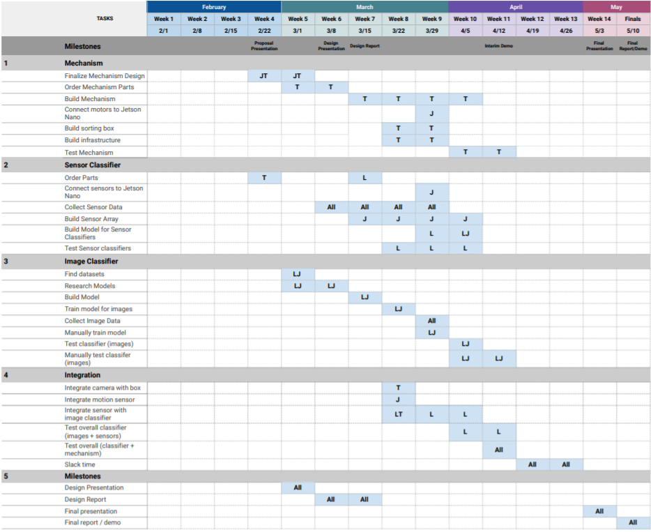
We are pushing back hooking up the motor and motor driver to the Jetson Xavier by a week (moving it from week 3/22 to 3/29). We have attempted to connect them this week, but didn’t get the motor to move yet.

Jessica’s Status Report for 3/27

This week, I helped to wire all of our inductive/capacitive sensors together and measure their output voltage/current to ensure that wiring that number of sensors in parallel would not damage the Jetson Xavier. I also continued downloading dependencies to the Jetson Xavier so that we could correctly interface with the motor driver, camera, sensors, and neural net model. I was able to hook up the Jetson Nano with the Raspberry Pi camera and a simple LED. Then, with Lauren,  I tested the motor driver and the sensors. We were able to hook up multiple inductive and capacitive sensors to the Jetson Xavier, but could not get the motor driver to drive our stepper motor.

My progress is slightly behind schedule. I underestimated the amount of time it would take to set up the Jetson Xavier and interface all of our sensors/motor with it. Installing PyTorch and all of its dependencies on the Jetson Xavier was also more challenging than I expected. However, after testing the sensors, my team realized that calibrating the sensors should take much less time than expected, so we were able to modify our schedule to account for the extra time spent connecting everything to the Jetson Xavier.

Next week, I hope to get the motor driver working successfully and finish installing the necessary machine learning libraries so that we can test the image classifier. Once that’s done, I can help build the sensor box and mount our sensors to it.

Tate’s Status Report for 3/13

This week I spent a lot of time preparing for our Design Review Presentation, which I gave on Wednesday. I also met with Jessica in the middle of the week to hash out any of our concerns on the design for the sliding mechanism. We discussed when certain parts of the mechanism would need to be purchased and then assembled as well. I am currently drawing/designing how our box will be mounted on the sliders, and I made a more detailed diagram of our sensor array with specific sensor sizes and spacing. I also met with all my team members and tested our sensors for around 3 hours on Saturday. I helped solder the ends of the inductive sensor wires to pieces of wire so that they would fit in our breadboard. I also helped with the wiring and connecting of our load sensor which my team hopes to have working this upcoming week.

Everything is on track for me except that I haven’t ordered the mechanism parts yet. Jessica and I narrowed down which parts we need to order, and decided that we don’t need to order them quite yet because we are not in a huge  hurry to assemble the slider. I do hope to order the mechanism parts though in the next week or so.

In the next week, I plan to complete my designated sections for our Design Review Report and also plan to finalize my drawing of how the box will be mounted on the sliding rails. I also plan to order the rest of our sensors and begin attaching them to the platform with my team.

Jessica’s Status Report for 3/13

This week, I mainly helped Tate prepare for the Design Review presentation and began working on the design report. I have added more detail to our system diagram and started filling out our BOM in more detail. I also decided to modify our mechanism to follow the design of a previous project of mine so that we can reuse parts and do not need to waste time CADing/3D-printing. We will need to slightly modify the mechanism’s dimensions, gear size, and moving platform to fit our project. From my calculations, a 1.65″ diameter gear with our 600rpm stepper motor should be able to meet our mechanism latency metric. The other modifications have also been accounted for. In addition to working on the mechanism, I met with my team today to begin testing our sensors. So far, all sensors except our load sensor have been tested.

My progress is currently on schedule. Next week, I hope to continue working on the design report. Then, I hope to start attaching the sensors to our platform and start building the image classifier.

Lauren’s Status Report for 3/13

This week, I helped update Tate on the sensor placement design, and helped him prepare for the design presentation by providing feedback on points he missed or needed to include during practice runs of the presentation. I also helped solder the wires used in the load sensors, and soldered the header pins onto the load sensor module. At a team meeting to test all of the sensors, I brought a bag of recyclables that included the different materials we needed to use to test all of the sensors (like metal cans, glass bottles, recyclable plastics, and paper cartons). I helped test some of the sensors by placing some of these objects close to each sensor. As of this week, all of the sensors except the load sensors were tested. I also started writing a rough draft with the key points of our classifier design and design requirements for the design report.

My progress is on schedule.

I hope to have the final draft of the classifier design (with a detailed software spec) in the design report next week, and start building the model for the image classifier.

Team Status Report for 3/13

The most significant risks are the sensing distances of some of the sensors the team tested. For example, the LDR sensor has a sensing range of 30 cm, but objects are only detected if they are directly placed above it. For this reason, we will change the number of each type of sensor on our platform to address this issue as well as possible. Some of the sensors also are not able to distinguish between the materials we want them to (such as the capacitance sensor for paper vs. non-paper materials), so we will need to either research another sensor to use for certain materials, or adjust the scope of the recyclable categories as needed. Other sensors may not be able to be used as intended (i.e. LDR sensor can’t detect all types of glass), so we may also change the type of sensor used for certain recyclable categories (i.e. use capacitance sensor for glass). Our contingency plan for the limited sensing ranges includes purchasing more sensors if budget allows.

The number of some of the types of sensors was changed, and we will be changing the way some recyclable categories are detected. After testing, the IR sensor was determined to be useless for the purposes of this project, since it can’t distinguish between any of the recyclable categories, so we may be removing it entirely from our system spec. Changing the number of other kinds of sensors was also necessary because some sensors cannot be used to distinguish between certain recyclable categories as intended. For example, the LDR sensor only is able to detect clear glass, not colored glass, so we may use capacitance sensors instead to detect all types of glass. The costs to this change are monetary, since certain sensors like capacitance sensors are more expensive than other kinds of sensors. These costs will be mitigated with further analysis of our budget as we finalize the number of the sensors we will use for each sensor type for the bottom of our platform (which the object goes into).

Here is a picture of the setup we used to test the sensors (this was the capacitance sensor):

Jessica’s Status Report for 3/6

This week, I focused on preparing our design presentation. For the slides, I mainly filled out the block diagram and  mechanical solution and implementation sides. With my group, I then met with our professor and the TA to discuss potential improvements to our presentation. After some advice from our TA to add more implementation details, Lauren and I met to finalize sensor placement and Jetson Nano GPIO allocation.

I also spent a lot of time finalizing the mechanism.  After deciding to reduce our target mechanism latency to <1s last week, I began researching different linear motor actuators. The main types of mechanisms I found were screwball, rack and pinion, and belt driven. It seems like all of these mechanisms are suitable for our use case given that we can adjust the mechanism speed based on gear sizes. I was also able to find CAD mechanisms for the rack and pinion and belt driven mechanisms so that we can hopefully laser cut most of our mechanism.

My progress is slightly behind. I focused most of my time on the hardware aspect of our project and on finalizing the slides, so I was not able to research different image classification models. Hopefully, we can use the resnet model that Lauren and I found a couple of weeks ago.

Next week, I hope to hook up our sensors to an Arduino and begin collecting data. Although we have a general idea of which stepper motors and motor drivers we want, we also need to submit the purchasing request.