Jonathan’s Status Report for Saturday, Apr. 11

This week I mainly worked on the network driver and microphone board hardware.

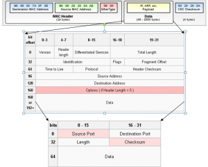
Last week, there was a problem that emerged with the network driver dropping up to 30% of the packets being transmitted from the FPGA, I spent most of this week working on resolving that.  The library being used previously was the “hypermedia.net” java library, which works well for low-speed data, but does not buffer packets well, and this was causing most of the drops.  By switching to linux and using the regular C network library, this problem was eliminated, though it required rewriting the packet processing and logging code in C.

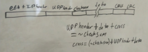
The next problem was moving this data to a higher-level language like java, python, or matlab to handle the graphics processing.  Initially, started looking into ways to give both programs access to the same memory, but this was complicated, not very portable, and difficult to get working.  Instead, I ended up deciding on using linux pipes/fifos, as they use regular file I/O, which c and java of course support very well.  One small problem that emerged with this had to do with the size of the fifo, which is only 64kB.  The java program had some problems with latency relative to the C program, so the FIFO was getting filled, and it was dropping readings.  To get around this, I modified the C program to queue up 50,000 readings at once, and put them into a single call to fprintf, and the java program reads in a similar way before processing any of the readings.  In this way, the overall throughput is improved, by having just 20 large, unbroken transfers per second, rather than several thousand smaller ones.  This does introduce some latency, though only 1/20th of a second which is easily tolerable, and takes more memory, but only a few megabytes.

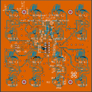
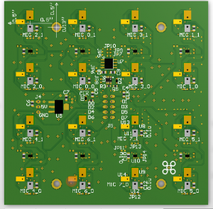
Progress on the hardware has mainly been in figuring out the process for manufacturing all the microphone boards.  There were initially some problems with the reflow oven blowing microphones off the board while the solder was still molten.  The fan used to circulate air to cool the chamber after it has reached its peak temperature has no speed control, and is strong enough in some areas to blow around the relatively large and light microphones.  So far, I have gotten the first few test microphones to work by reflowing them by hand with hot air, which worked but took a significant amount of work per microphone, so it may not be a viable solution for the whole array.  I have started working on adding speed control and/or flow straighteners to the reflow oven fan as well, though I suspect I’ll be in for a long day or two of soldering.

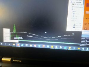
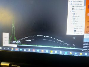
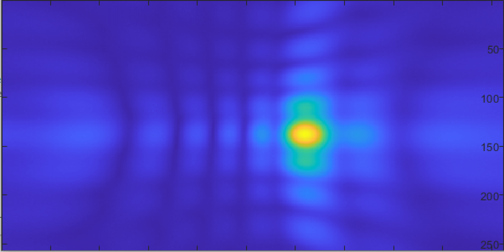
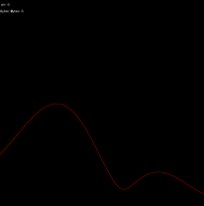
With the working test board, I was able to use the real-time visualizer to do some basic direction finding for a couple of signals, which were extremely promising:

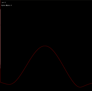
5KHz, high resolution, centered in front of the array (plot is amplitude vs direction)

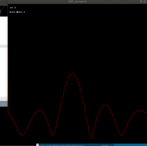
5KHz, high resolution, off-center (about 45 degrees)

Low resolution, 10KHz centered in front of the array

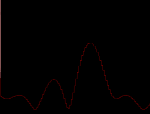
10KHz, low resolution, about 15 degrees off center.

Next week I mainly plan to focus on the hardware, mainly populating all of the microphones and making the wiring to the FPGA.

Sarah’s Status Report for Saturday, Apr. 11

This week, we presented our midpoint demo. The demo went well with the visualization of a sound source in real-time. I also worked on writing the existing code into python. Since we found that the logfiles we were working with possibly had errors, I didn’t move on to the localization of sound source since making sure the existing processing worked was important. As I have received new logfiles for simulation, I believe the results will be better shown compared to last time.

Next week, I look forward to doing some testing with the logfiles to see if the output looks as we assumed. If there is time, I will be working on visualizing the sound source.

Ryan’s Status Report for Saturday, Apr. 11

I’m waiting for the 96 microphones to be assembled. Once all of them are functional, I’m going to calibrate them by having John capture their output with a sound source of three tones at 2563Hz, 8667Hz, and 12597Hz.  These three frequencies we were observed from the recording of the air leak, so we will focus on these.

The sound will be played through a bluetooth speaker approximately 8-10ft away from the microphone array to minimize the variations in distances between the microphone and the sound source. If the speaker were much closer, the angle between the microphone array and the speaker will have a larger variance, as well as the distance between the mic and the speaker, since the microphone array is flat, not curved.

In the microphone’s datasheet, it lists the maximum sensitivity variation to be +/- 1dB, so they should be pretty close to each other.

The most basic calibration will involve taking the average of the three tones’s output level and simply adding or subtracting an offset to compensate for the sensitivity of the microphone.

If we find significant differences in sensitivity from one microphone to the next depending on the frequency, we will have to generate an equalization factor that is dependent on frequency, such as in a graphic EQ.

Next week:

Get the microphone array assembled and perform the calibration procedure.


Sarah’s Status Report for Saturday, Apr. 4

This week, I mainly worked on time-domain delay and sum beamforming. I was able to make the simulation output. I received a 5khz and 10khz log files from John and processed for 96 channels, 8 by 12 array and 1-inch spacing parameters. The output is shown below.

However, I realized later that the logfiles are actual data from just 2 microphones. After adjusting to the correct parameters, the resulting output was below which didn’t seem to match out the assumption that there should be a single spike at 5khz. Major problems and problem fixes can be found in John’s Status report.

For next week, I will focus on writing a visualization for a heat map for the data.

Ryan’s Status Report for Saturday, Apr. 4

This week I continued my work on synthesizing sounds of air leaks. I used a recording of a real air leak, performed an FFT on it, identified the peak frequencies in the audio, and created various variants of it.

As mentioned in last week’s update, the three peeks are at the following frequencies and amplitudes:

2563Hz: -24dB

8667Hz: -18dB

13597Hz: -17dB


I created waveforms of pure sine tone at 2563, 8667, and 13597Hz in three separate WAV files.

If all goes well, the phased array should be able to detect and physically locate the first two tones. The third tone’s wavelength is shorter than the distance between each microphones in the array, so it would be aliased. This is outside our frequency specification range, so the device should filter it out to prevent aliasing artifacts from appearing.


Next, I generated a Gaussian-distributed noise source centered at  approximately 2563, 8667, and 13597Hz in three separate WAV files.

They have the following frequency distributions:

They sound like this, in the order of increasing frequency:

The noise floor isn’t audibly low, and this is intentionally done to best match real world environments. If all goes well, the system should be able to detect and locate the first two tones even with the high noise floor.

Further work:

Reflow the 96 microphones and auxiliary components into the PCB and hook them up to the FPGA.

Test the system with the synthesized frequencies.

Team Status Update for Saturday, Apr. 4

This week significant progress made in all areas of the project, including the hardware/FPGA component catching back up to the planned timeline.

To prepare for the midpoint demo on Monday, all group members have been working on getting some part of their portion of the project to the point where it can be demonstrated.  John has a working pipeline to get microphone data through the FPGA and into logfiles, Sarah has code working to read logfiles and do some basic processing, and Ryan has developed math and code that works with Sarahs to recover the original audio.

While at this point the functionality only covers basic direction-finding, this bodes well for the overall functionality of the project once we have more elements and therefore higher gain, directionality, and the ability to sweep in two dimensions.  The images below show basic direction-finding, with sources near 15 degrees from the element axis (due to the size of the emitter, placing it at 0 was impossible), and near 90 degrees to the elements.  The white line plots amplitude over angle, and so should peak around the direction of the source, which it does:

~15 degrees:

~90 degrees:

This coming week should see significant progress in the hardware, as we now have all materials required, continued refinement of the software, as most of the major components are now in place.

Jonathan’s Status Report for Saturday, Apr. 4

This week I mainly worked on updating the FPGA firmware and computer network driver.  Boards arrived yesterday, but I haven’t had time to begin populating them.

Last week, the final components of the network driver for the FPGA were completed, this week I was able to get microphone data from a pair of microphones back from it, do very basic processing, and read it into a logfile.  This seemed to work relatively well:

source aligned at 90 degrees to the pair of elements (white line peaks near 90 degrees, as it should)

source aligned at 0 degrees to the pair of elements (white line has a minimum near 90 degrees, again as it should)

However, these early tests did not reveal a problem in the network driver.  Initially, the only data transmitted was the PDM signal, which varies essentially randomly over time, so as long as some data is getting through, so it is very difficult to see any problems in the data without processing it first.  Several days later when testing some of the processing algorithms (see team and Sarahs updates), it quickly became apparent that something in the pipeline was not working.  After checking that the code for reading logfiles worked, I tried graphing an FFT of the audio signal from one microphone.  It should have had a single,  very strong peak at 5KHz, but instead, had peaks and noise all over the spectrum:

I eventually replaced some of the unused microphone data channels with timestamps, and tracked the problem down to the network driver dropping almost 40% of the packets.  While Wireshark verified that the computer was able to receive them just fine, there was some problem in the java network libraries I had been using.  I’ve started working on a driver written in C using the standard network libraries, but haven’t had time to complete it yet.

Part of the solution may be to decrease the frequency of packets by increasing their size.  While the ethernet standard essentially arbitrarily limits the size of packets to be under 1500 bytes, most network hardware also supports “jumbo frames” of up to 9000 bytes.  According  to this : https://www.google.com/url?sa=t&rct=j&q=&esrc=s&source=web&cd=6&ved=2ahUKEwjrx8zAvM_oAhUvhXIEHcBHDmYQFjAFegQIBxAB&url=https%3A%2F%2Farxiv.org%2Fpdf%2F1706.00333&usg=AOvVaw1OaEu0ozlfTlaN1ZTfb-IW     paper, increasing the packet size above about 2000 bytes should substantially lower the error rate.  So far I’ve been able to get the packet size up to 2400 bytes using jumbo frames, but I have not finished the network driver in order to test it.

Next week I mainly plan to focus on hardware, and possibly finish the network driver.  As a stop-gap, I’ve been able to capture data using wireshark and write a short program to translate those files to the logfile format we’ve been using.

Ryan’s Status Report for Saturday, Mar. 28

This week I’ve worked on synthesizing a recording of an air leak for use in our performance testing and validation.

First, I downloaded an air leak sound effect and imported it in Audacity:

I then amplified it and kept only the middle portion where the leak noise was consistent:

I did an FFT to get an idea of the main frequency content:

We have peaks in the following locations:

2563Hz: -24dB

8667Hz: -18dB

13597Hz: -17dB

I then created an EQ profile to apply to a white noise source:

After applying the EQ to white noise, we get an FFT:

This looks very close to our original leak. We can use this synthesized sound to test the system after we verify it with a single tone sine wave. The synthesized source can act as an intermediary between the single tone and a real recording of a leak because this is more complex than a single tone, but less complex than the sound of a real leak.

Further work:

Deeper analysis into what sounds the system detects well and which sounds the system does not perform well with, and why.

Compare and contrast real world air leak recordings and synthesized versions.

Jonathan’s Status Report for Saturday, Mar. 28

This week I mainly worked on the microphone boards and FPGA drivers.  The microphone boards were finished early this week, and ordered on Wednesday.  They were fabricated and shipped yesterday, and expected to arrive by next Friday (4/3).

As mentioned previously, this design uses a small number of large boards with 16 microphones each, connected directly to the FPGA board with ribbon cables.  This should significantly reduce the amount of work required to fabricate the boards and assemble the final device, though at the expense of some configurability, if we have to change some parameter of the array later.

As the schematic shows, most of the parts on the board will not be populated, but were included as mitigations to possible issues.  The microphone footprints were included in case we need to change microphones, and there are several different options for improving clock and data signal integrity (such as differential signaling and termination), if needed.  Most parts, particularly the regulator, are relatively generic, and so can be acquired from multiple vendors, in case there is a problem with our digikey order (which was also placed this week).

While working on the FPGA ethernet driver, one problem that came up was with the UDP checksum.  Unlike the ethernet frame CRC, which is in the footer of the packet, the UDP checksum is held in the packet header:

This means that the header depends on all of the data to be sent, which, means that the entire packet must be held in memory, then the checksum computed, then either the checksum modified in memory before transmission, or, during transmission the “source” of data has to be changed from memory to the register holding the checksum.  I didn’t particularly like either of these solutions, and so, came up with another.  I made the checksum an arbitrary constant, and added two bytes to the end of the UDP payload.  Those two bytes, which I termed the “cross”, are computed based on all of the data, and the header, so that the checksum works out to that constant.  The equation below isn’t exactly right, but gives the basic idea:

In this way, the packet can be sent out without knowing it’s entire contents ahead of time.  In fact, if configured to do so, could actually take in new microphone data in the middle of the transmission of a packet, and include that in the packet.  This greatly simplifies the rest of the ethernet interface controller, at the expense of a small amount of data overhead in every packet.  Given the size of the packets though, this tradeoff is easily worth it.

This coming week, I mainly plan to work on getting the information flow, all the way from the FPGA PDM inputs to a logfile on a computer working.  This was expected to be completed earlier, but the complexity of ethernet frames ended up being significantly greater than expected, and took several long days to get working.  At this point all the components of the flow are working to some degree, but do not work together yet.

Team Status Update for Saturday, Mar. 28

This week largely saw a return to a more normal work schedule, and beginning to act on the updated plan.

Our new timeline to account for the recent changes is shown below:

Most components are on track or completed, though there are several components which have fallen slightly behind.  Mainly the computer-side driver to receive and decode data from the FPGA, and the array processing software.  To help get back on track, and since much of the audio calibration/testing has been removed from the scope of the project, Ryan has become more involved with the software/processing side.  John also plans to finish the network driver this weekend.

On the hardware side, the architecture of the physical architecture was slightly changed to simplify the design.  Specifically, from having a single carrier board with connectors for each microphone element, to having a small number of boards with many microphones each, that connect directly to the FPGA board using ribbon cables.

Our risk management has largely been reduced the last few weeks, as most of the main risks we foresaw were eliminated over the course of the project so far, or, did not end up being issues.  Our PCB and digikey orders have been fulfilled already, so unless there are problems with shipping, we should have the necessary hardware.  If there are any problems, board design includes several generic alternatives for each critical part, so as long as at least one supplier remains open, we should be able to finish the hardware (see John’s update for more details).  On the software side, risks and mitigations have not changed.