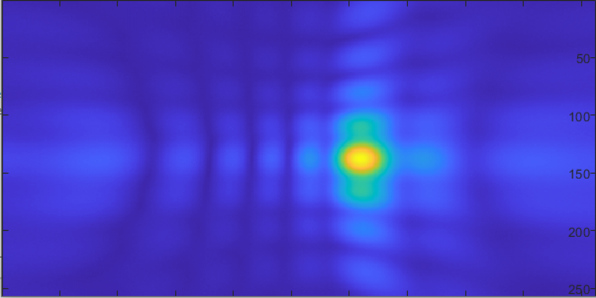
This week I mainly finished the hardware and continued refining the real-time imaging.
The hardware was half completed at the beginning of this week, with 48 microphones assembled on their boards and tested. At the beginning of this week I assembled the remaining 48.
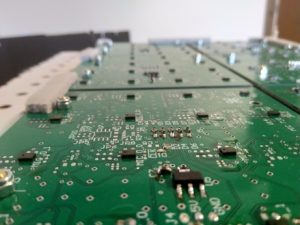
Since the package for these microphones, LGA_CAV, are very small, with a sub-mm pitch, and no exposed pins, soldering was difficult and often required rework. Several iterations of the process to solder them were used, beginning with a reflow oven, eventually moving to hot air and solder past, then manual tinning followed by hot air reflow. The final process was slightly more time consuming than the first two, but significantly more reliable. In all, around 20% of the microphones had to be reworked. In order to aid in troubleshooting, a few tools were used. The first was a simple utility I wrote based on the real-time array processor, which examined each microphone for a few common failures (stuck 0, stuck 1, “following” its partner, and conflicting with its partner).
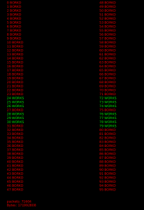
This image shows the output of this program (the “bork detector”) for a partially working board. Only microphones 24-31 and 72-79 are connected (a single, 16-microphone board), but 27,75, and 31 are broken. This enabled quickly determining where to look for further debugging.
The data interface of PDM microphones is designed for stereo use, so each pair takes a single clock line, and has a single digital output for both. Based on the state of another pin, each “partner” outputs data either on the rising or falling edge of the clock, and goes hi-z in the other clock state. This allows the FPGA to use just half as many pins as there are microphones (in this case, 48 pins to read 96 microphones). Often the errors in soldering could be figured out based on this.
Using an oscilloscope, a few common errors could quickly be identified, and tracked to a specific microphone, by probing the clock line and data line of a pair (blue is data, yellow clock):
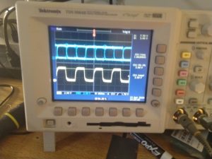
Both microphones are working
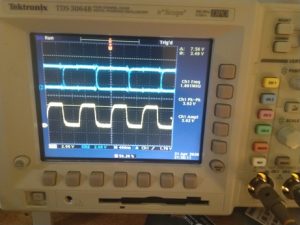
The falling-edge microphone is working, but the data line of the rising-edge microphone (micn_1) is disconnected
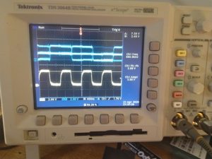
The falling-edge microphone is working, but the rising-edge microphone’s select line is disconnected.
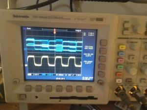
The falling-edge microphone is working, but the rising-edge microphone’s select line is connected to the wrong direction (low, where it should be high).
The other major thing that I worked on this week was refinements to the real-time processing software. The two main breakthroughs here that allowed for working high-resolution, real time imaging was using a process which I’ll refer to as product of images (there may be another name for this in the literature or industry, but I couldn’t find it), and frequency-domain processing.
Before using product of images, the images generated by each frequency were separate, as in this image where two frequencies (4000 and 6000Hz) are shown in two images side by side:
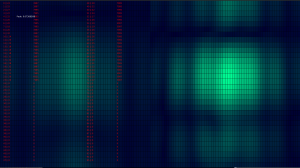
Neither image is particularly good on its own (this particular image also used only half of the array, so the Y axis has particularly low gain). They can be improved significantly by multiplying two or more of these images together though. Much like how a Kalman filter multiplies distributions to get the the best properties of all the sensors available to it, this multiplies the images from several (typically three or four) frequencies, to get the small spot size of the higher frequencies, as well as the stability and lower sidelobes of lower frequencies. This also allows a high degree of selectivity, a noise source that does not have all characteristics of the source we’re looking for will be reduced dramatically.
For a simple example, suppose we have a fan that has relatively flat (“white”) noise from 100Hz – 5KHz, and 10dB lower noise above 5KHz (these numbers based roughly on the fan in my room). If the source we’re looking at has strong components at 2,4,6,and 8 KHz, and the two have roughly equal peak signal power, then “normal” time domain processing that adds power across the entire band would have the fan be vastly more powerful than the source we’re looking for, as the overall signal power would be greater because of the very wide bandwidth (4.9KHz bandwidth as opposed to just a few tens of Hz, depending on the exact microphone bitrate). Doing product of images though would have the two equal at 2 and 4KHz, but would add the 10dB difference at both 6 and 8KHz, in theory giving a 20dB SNR over the fan. This, for example, is an image created from about 8 feet away, where the source was so quiet my phone microphone couldn’t pick it up more than 2-3 inches away:
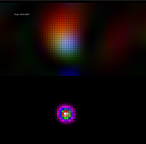
In practice this worked exceptionally well, largely cancelling external noise, and even some reflections, for very quiet sources. Most of the real-time imaging used this technique, some pictures and videos also took the component images and mapped each to a color based on its frequency (red for low, green for medium, blue for high), and just made an image based on these. In this case, artifacts at specific frequencies were much more visible, but it did give more information about the frequency content of sources, and allowed identifying sources that did not have all the selected frequencies. In the image above, the top part is an RGB image, the lower uses product of images.
Finally, frequency domain processing was used to allow very fast operation, to get multiple frames per second. Essentially each input channel is multiplied by a sine and cosine wave, and the sum of each of those waves over the entire input duration (typically 50mS) is stored as a single complex number. So for a microphone, if f(t) is the reading (1 or -1) at time t, and c is the frequency we’re analyzing divided by the sample rate, then this complex number is given by f(0)*cos(c*0) + f(1)*cos(c*1) … + f(n)*cos(c*n) + f(0)*sin(c*0)*j + f(1)*sin(c*1)*j + f(n)*sin(c*n)*j. Once all of these are computed, they’re approximately normalized (any values too small are kept small, larger values are kept relatively small, but allowed to grow logarithmically). To generate images, a phase table, which was precomputed when the program first started, is used to map a phase offset for each element, for each pixel. This phase delay is proportional to the frequency of interest, and what the time delay would have been if we were doing time domain delay-and-sum. Each microphone’s complex output value is multiplied by a value with this phase and magnitude 1, and then those numbers are summed, and the amplitude taken, to get a value for that pixel in the final image. While significantly more complicated than delay-and-sum, and much more limited as it can only look at a small number of specific frequencies, this can be done very quickly. The final real-time imaging program was able to achieve 2-3 frames per second, where post-processing in the time domain typically takes several seconds (or even minutes, depending on the exact processing method being used).
