This week, I wrapped up the circuit design for the motor controller and did the layout for the motor power supply.
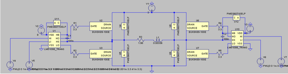
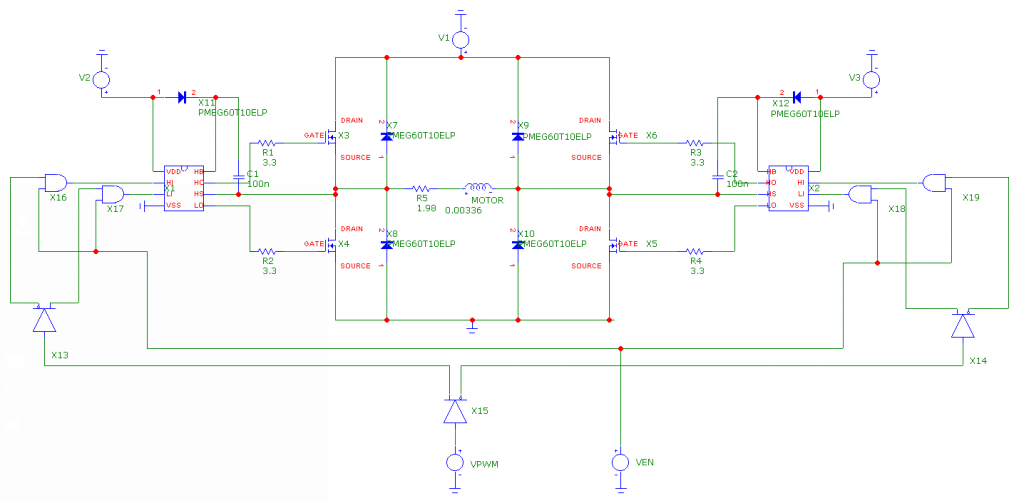
Since the majority of the motor controller circuit (up to the H-bridge gate driver ICs) had been simulated in LtSpice, what remained was the design of the chain of logic gates designed to reduce the 4 individual control inputs of the H-bridge gate driver chips to a single PWM pin with an ENABLE input. This was quickly accomplished by finding a logic buffer with delay-equalized complementary outputs (the CD4041UB chip) and a quadruple AND gate for implementing the ENABLE input (SN74HC08).
However, I was unable to simulate the full motor controller circuit until very recently, as the PSPICE model I found for the logic buffer was incompatible with LtSpice (the circuit simulator I had been using to work on the motor controller). Luckily, I found that the recently free Micro-cap simulator had functional models for both digital chips, and set up the following testbench for calculating the motor controller’s overall propagation delays:
Transient simulation with a handful of rising and falling edges at the PWM and ENABLE inputs produced the following plot:
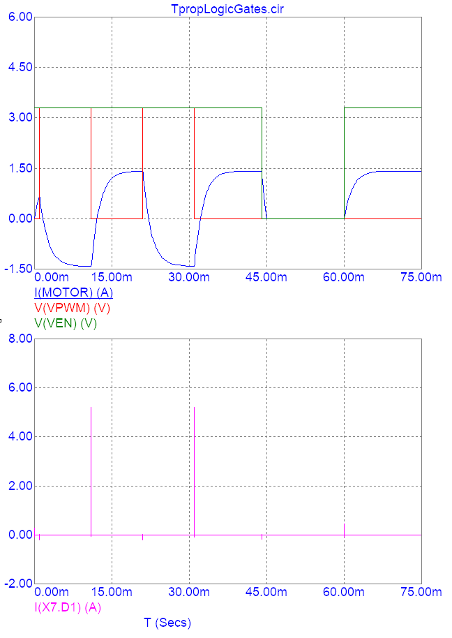
Using the top set of waveforms, I determined that the PWM input’s rising propagation delay was 1.13 ms, while the falling propagation delay was 1.11 ms. Similarly, I found that the ENABLE input’s rising propagation delay was 1.12 ms, while the falling propagation delay was 0.41 ms. This did not change much when I conducted a worst case analysis with the simulation’s logic delay models. Since these values are consistent with the timing delays I had calculated in LtSpice without the logic gates, there is little reason to doubt the accuracy of the simulation.
Since these delays are insignificant in comparison to the periods with which the equatorial mount stepper motors will be actuated (0.3 sec), we will not have to take them into account when programming the equatorial mount.
Furthermore, I’ve confirmed that the flyback diodes I selected for absorbing voltage spikes at the H-bridge output are adequate. Judging from the lower graph, the most an individual diode will experience is a current spike up to ~5 A, which is substantially lower than the diodes’ non-repetitive peak forward current rating (35 A).
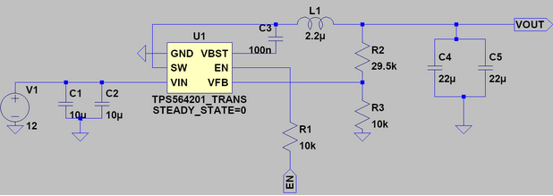
Lastly, I’ve finished laying out a PCB for the stepper motors’ 3V 4A power supplies:
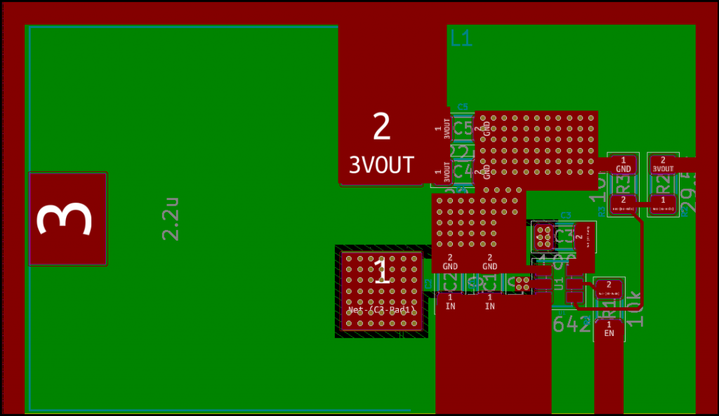
The layout was performed in accordance with the guidelines that were laid out in the buck converter’s datasheet, and no major current-carrying trace has a width lower than 40 mils (the width required for 4A of current to cause a maximum of 10 degrees C of temperature rise with 2 oz. of air-exposed copper). The resulting “standard cell” can be dropped into a standalone instance of PCBnew (KiCad’s layout utility) for integration with the motor controller section. As can be seen, the 3V output is available on 3 sides of the cell for ease of placement in the future. Major current-carrying traces will be exposed to air instead of being covered by solder mask.
Unfortunately, I am behind on my schedule. I have yet to make progress with selecting a gyroscope, which I’ll need to finish up next week after consulting with Kenny on the required precision. Fortunately, this involves minimal circuit design, so catching up will be fairly simple.
Next week, I’ll need to design and layout a 8V buck converter for powering the motor controller ICs, in addition to laying out the actual motor controller in KiCad. This 8V buck converter will be laid out in the same manner as the 3V power supply shown above, although it will be easier to design due to the lower current requirement. Due to this, I do not plan to provide an ENABLE input for it in the layout.
The primary concern at this stage of the design is the layout of the motor controller H-bridges. If there is too much parasitic inductance, there is a possibility that the H-bridge MOSFETs will experience a shoot-through failure condition, destroying them. I plan on including diodes in shunt with the MOSFET gate resistors so that they turn on slower than they turn off (introducing a sort of dead time into the operation of the motor controller). If this fails, I can simply find a motor controller on Digikey that satisfies our requirement.