
This week, I set up a basic framework for the Worker Finder using the UDP communications protocol. I tested this feature by setting up a server and sent messages back and forth between the Worker finder and the server. The server in this case acts as a Rasp Pi. There is still a little bit of work left to do on the Worker Finder as I am unclear about some of the very specific details of the implementation. This coming week, I plan on working with Jared to hash out these details as he in charge of the Bus Protocol. I also plan on working on the Workload Manager, specifically using the third party tool that I found a couple weeks back to measure the size of a model given the input parameters.
Jared’s Status Report for Mar. 28
This week I wrote an initial draft of the SPI slave SystemVerilog code. Todo is the code to faciliate data transfer betwenn the Ethernet and SPI. This should meet the mark where we can put our pieces together, however I would still need to write some tests.
I received the parts for the setup this week. I will be connecting them to the host desktop for us to use and test on.
In relation to TJ I have been slacking a bit on code. I hope to meet with him once this section is done and work on the meat and bones of the project a bit more.
Theodor’s Status Update for Mar. 28
Accomplishments
This week I accomplished one of the hard parts of the FPU job manager: writing the FSM for the Convolutional Forward module.
It’s worth mentioning that there were easier options for implementing Convolutional Forward than to define the operation in an FSM. We could have chosen to write convolutional forward in C, compile it to RISCV-assembly, and copy the code to our FPGA and use that, but this would require precious on-board memory that we need to store input samples. Writing Convolutional forward as an FSM is the fastest and smallest solution to our problem, and doing so will maximize our model throughput. Convolutional backward (gradient with respect to the inputs, filters, or bias) are essentially the same nested loops above, so implementing those operations will be significantly easier if I use the code above as a starting point.
I now know the exact requirements that the FPU Job Manager needs: 32×32-bit registers that can be accessed with multiple reads and multiple writes per cycle (I will have to declare an array of registers and expose all of the wires instead of writing a Register File), and some specific ALU/FPU instructions:
- offset = channel_index + (num_channels * i) + ((num_channels * image height) * j)
- x = x + 1 (integer increment)
- x = y + z (integer addition)
- floating-point multiply
- floating-point addition
Like I mentioned last week, having Convolutional Forward completely defined will cause a lot of other pieces to fall into place. Next week, I plan on implementing some of these ALU/FPU and register requirements in SystemVerilog.
Here’s what my definition looks like:
pseudocode:

w_o_fac <- x.height * x.channels

j <- 0
j_x <- (-1 * pad)
while(j < z.width):
  w_o <- w_o_fac * j_x
  i <- 0
  i_x <- -1 * pad
  while(i < z.height):
    beta <- 0
    while(beta < f.width):
      alpha <- 0
      while(alpha <- f.height):
        gamma <- 0
        while(gamma < f.in_channels):
          delta <- 0
          while(delta < f.out_channels):
            z[delta, i, j] <- z[delta, i, j] + (f[delta, gamma, alpha, beta] * x[gamma, i_x + alpha, j_x + beta])

            delta <- delta + 1

          gamma <- gamma + 1

        alpha <- alpha + 1

      beta <- beta + 1

      delta <- 0
      while(delta <- z.channels):
        z[delta, i, j] <- z[delta, i, j] + b[delta]

        delta <- delta + 1

    i <- i + 1
    i_x <- i_x + stride

  j <- j + 1
  j_x <- j_x + stride


State transitions:

// STATE == START_LOAD1
r1 <- stride
r5 <- filter.output_channels
r9 <- x.height
nextState = START_LOAD2


// STATE == START_LOAD2
r2 <- pad
r6 <- filter.input_channels
r10 <- x.width
nextState = START_LOAD3


// STATE == START_LOAD3
r3 <- output_height
r7 <- filter.height
nextState = START_LOAD4


// STATE == START_LOAD4
r4 <- output_width
r8 <- filter.width
*z <- output_height
z++
nextState = START_CALC


// STATE == START_CALC
*z <- output_width
z++
r11 <- r9 * r6         // w_o_factor = x.height * x.channels
r12 <- ~r2 + 1         // j_x = -1 * pad
r19 <- 0               // j = 0
nextState = J_LOOP


// STATE == J_LOOP
r13 <- r11 * r12
if(r19 == r4):         // if j == z.width
  nextState = DONE
else:
  r21 <- 0             // i = 0
  r20 <- ~r2 + 1       // i_x = -1 * pad
  nextState = I_LOOP


// STATE == I_LOOP
if(r21 == r3):         // if j == z.height
  r19 <- r19 + 1       // j += 1
  r12 <- r12 + r1      // j_x += stride
  nextState = J_LOOP
else:
  r22 <- 0             // beta = 0
  r28 <- r20 * r6      // r28 = f.input_channels * i_x
  nextState = BETA_LOOP


// STATE == BETA_LOOP
if(r22 == r8):         // if beta == f.width
  r25 <- 0             // delta = 0
  z <- z - r5          // Reset z counter, we’re going to iterate over channels again
  b <- 2
  nextState = BIAS_LOOP_LOAD
else:
  r23 <- 0             // alpha = 0
  nextState = ALPHA_LOOP


// STATE == ALPHA_LOOP
if(r23 == r7):         // if alpha == f.height
  r22 <- r22 + 1
  nextState = BETA_LOOP
else:
  r24 <- 0             // gamma = 0
  nextState = GAMMA_LOOP


// STATE == GAMMA_LOOP
if(r24 == r6):        // if gamma == f.input_channels
  r23 <- r23 + 1      // alpha = 0
  nextState = ALPHA_LOOP
else:
  r25 <- 0            // delta = 0
  r27 <- r24 + (r6 * (r20 + r23)) + (r11 * (r12 + r22)) // x offset
  nextState = DELTA_LOOP_LOAD


// STATE == DELTA_LOOP_LOAD
r14 <- *z             // r14 <- z[delta, i, j]
r15 <- *f             // r15 <- f[delta, gamma, alpha, beta]
r16 <- *r27           // r16 <- x[gamma, i_x + alpha, j_x + beta]
if(mem(z).done && mem(f).done && mem(x).done):
  nextState = DELTA_LOOP_CALC1
else:
  nextState = DELTA_LOOP_LOAD


// STATE == DELTA_LOOP_CALC1
  r17 <- r15 * r16    // r17 <- f[delta, gamma, alpha, beta] * x[gamma, i_x + alpha, j_x + beta]
  nextState = DELTA_LOOP_CALC2


// STATE == DELTA_LOOP_CALC2
  r18 <- r14 + r17   // r18 <- z[delta, i, j] + (f[delta, gamma, alpha, beta] * x[gamma, i_x + alpha, j_x + beta])
  nextState = DELTA_LOOP_STORE

// STATE == DELTA_LOOP_STORE
*z <- r18
if(mem(z).done && r25 == r5): // if(memory is done writing and delta == f.output_channels)
  r24 <- r24 + 1
  nextState = GAMMA_LOOP
else if(mem.done):
  nextState = DELTA_LOOP_STORE
else:
  r25 <- r25 + 1        // delta += 1
  z++
  f++
  nextState = DELTA_LOOP_LOAD


// STATE == BIAS_LOOP_LOAD
r14 <- *z               // r14 <- z[delta, i, j]
r15 <- *b               // r15 <- b[delta]
if(mem(z).done && mem(b).done):
  nextState = BIAS_LOOP_CALCS
else:
  nextState = BIAS_LOOP_LOAD

// STATE == BIAS_LOOP_CALCS
r16 <- r14 + r15
nextState = BIAS_LOOP_STORE

// STATE == BIAS_LOOP_STORE
*z <- r16
if(mem(z).done && r25 == r5):
  z++
  b++
  r21 <- r21 + 1       // i += 1
  r20 <- r20 + r1      // i_x += stride
  nextState = I_LOOP
else if(mem(z).done):
  r25 <- r25 + 1
  nextState = BIAS_LOOP_LOAD
else:
  nextState = BIAS_LOOP_STORE

// STATE == DONE
Schedule
I remain on the schedule that I proposed last week.
Accomplishments for Next Week
Next week will be time to start implementing the FPU Job Manager. Now that I know the upper limit for the resources that the FPU Job Manager needs, I can be confident that I won’t have to redesign it. Although I only have a couple of FSM controllers defined, I want to go ahead with the implementation so that I can solve any unexpected problems related to SystemVerilog implementation of the modules and memory accesses.
Team Status Update for March 28
Contingencies (Risk Management)
Due to the instability of the situation, we need to plan for the contingency that our necessary hardware cannot be shipped to us. We are already planning to calculate clock cycles necessary to perform essential hardware operations in simulation. We can calculate the model throughput of the entire system using numbers acquired in simulation:
We can calculate an estimate of the model throughput of the system using the following method:
|
`
Ta = Nm * (LB) + (LD) Tt1 = (C1) * (50M clock cycles per second) TN = N * Tt1 M1 = NM / (Ta + TN) MN = sum of M1 for each board in use |
Our simulated estimate for model throughput can then be compared to the model throughput of the CPU and GPU hardware setups, in case we are not able to build the system and measure an end-to-end metric.
The rest of our Team Status Update is below:
Accomplishments
Theodor fully defined a control FSM for the Convolutional Forward FPU operation, which also defines the upper limit of requirements for the FPU Job Manager (i.e. how many registers are needed, whether specific ALU operations are necessary).
Mark finished a framework for the Worker Finder, using a UDP broadcast as discussed and verifying the framework using a local server that emulates the Rasp Pi.
Schedule and Accomplishments for Next Week
Theodor will begin implementing the FPU Job Manager in SystemVerilog.
Mark will be working on the Workload Manager.
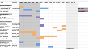
Updated Gantt Chart
Jared’s Status Report for Mar. 21
With the recent events, retrieving the DE0-Nano for testing after spring break wasn’t possible. While we are able to put together some of the initial hardware, we have dedicated work to verification of the code. As such, the validation will be split into two sections:
1. RPi Ethernet packet transfer
This test is essentially the program itself. A dummy routine will replace the SPI protocol in order to verify that packets are correctly processed.
2. FPGA data transfer
The RPi is communicating through SPI bus, which is thankfully incredibly easy to mimic in verilog. A testbench will require validating both sending and receiving data across the clock domains (125 MHz from SPI, 50 MHz from the DE0-Nano).
The RPi does not need a SPI test, as an external library handles the read and write calls.
This is incredibly behind schedule, but we live in incredible times. I’ll make sure to at least get the RPi Ethernet packet transfer test working.
On a side note, I am repurposing an old desktop as a SSH server for the team. It and the Pi will have internet access. I am taking precautions for the Pi, as I am aware that having an open interface with the username “pi” is unwise.
Theodor’s Status Update for Mar. 21
Accomplishments
I wasn’t able to post a status update before spring break started, but that doesn’t mean I haven’t been busy. This week I have two big accomplishments to report:
- Implemented Memory Port Controller Cache
- Started Defining FPU Job Manager Control FSMs
First, the cache code is the part of the Memory Port Controller that will actually be sending signals to the SDRAM and M9K Controllers. Having the cache implemented means that implementing the rest of the Memory Port Controller is simply a matter of instantiating modules and writing an if statement to route read/write enable signals.
Second is the matter of the FPU Job Manager Control FSMs. Actually solidifying the number of FPUs a Job Manager, deciding how many registers to put in a register file, and determining how many writes to registers to perform in a cycle depends on the necessities we need to perform the Linear Forward, Convolution Forward, and Convolution Backward operations defined in our Design Document. Every other operation is simpler than these, so an implementation of the FPU Job Manager that accommodates for all of these three operations will also have ample resources to perform the rest. In addition, since most of the other operations are very simple, writing the rest of the FPU Job Manager will be a much simpler task.
At the moment, the definition of a control FSM looks like this:
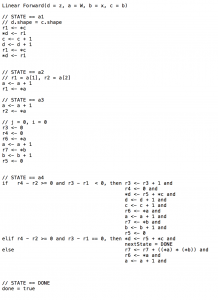
Essentially, it describes the number of states needed, the actions performed in each state, and the transitions between states. It is necessary to do this before I actually write the code so that I know the maximum requirements needed by any FPU operation and I can write the Job Manager to have the smallest footprint possible.
Schedule
The Memory Port Manager is something that should have been finished before this week. By my next status update, it will be completely done.
Accomplishments for Next Week
For next week, the Memory Port Manager will be complete and the FSM definitions for the Linear Forward, Convolution Forward, and Convolution Backward layers will be complete. Ideally, I will be implementing the FPU Job Manager next week.
Mark’s Status Report for March 21st
This week, I was able to provide preliminary numbers on the training result of our model test set on a GPU, as well as a different, higher end CPU as well. The full statistics can be seen at the bottom of the status report. The main takeaway is that although the GPU and CPU have almost the same average time, wider models trained much faster on the GPU than the CPU. Likewise, deeper models trained faster on the CPU. Additionally, I also realized that I was not fully utilizing the GPU when training each model sequentially. A possibility that I would like to explore in the future would be to possibly train multiple models simultaneously on a GPU to maybe get a better average throughput.
I also worked with TJ and Jared to write up the Statement of Work as well as figuring out what our plan for the project was in the future. During this stage, I more concretely defined what I would be doing in order to validate the Software portion of our project. These methods are more clearly defined in the Team Status Report.
I would say I am on schedule this week.
This coming week, I plan to start working on setting up a form of validation for the software portion of the Project.
Hardware: NVIDIA GeForce RTX 2060 SUPER
Trained models with an average throughput of 24.454581
Trained models at an average time of 40.866 seconds
Model 1 stats: Time taken: 28.239 seconds, Loss value: 966.509
Model 2 stats: Time taken: 24.933 seconds, Loss value: 732.629
Model 3 stats: Time taken: 25.145 seconds, Loss value: 804.955
Model 4 stats: Time taken: 30.565 seconds, Loss value: 727.075
Model 5 stats: Time taken: 38.075 seconds, Loss value: 749.385
Model 6 stats: Time taken: 48.607 seconds, Loss value: 852.541
Model 7 stats: Time taken: 50.306 seconds, Loss value: 852.214
Model 8 stats: Time taken: 55.584 seconds, Loss value: 902.778
Model 9 stats: Time taken: 60.663 seconds, Loss value: 1151.682
Model 10 stats: Time taken: 65.919 seconds, Loss value: 1150.963
Model 11 stats: Time taken: 24.625 seconds, Loss value: 674.633
Model 12 stats: Time taken: 24.847 seconds, Loss value: 617.159
Model 13 stats: Time taken: 25.726 seconds, Loss value: 606.477
Model 14 stats: Time taken: 32.640 seconds, Loss value: 566.784
Model 15 stats: Time taken: 37.984 seconds, Loss value: 590.729
Model 16 stats: Time taken: 29.991 seconds, Loss value: 1055.854
Model 17 stats: Time taken: 30.329 seconds, Loss value: 965.328
Model 18 stats: Time taken: 30.178 seconds, Loss value: 992.295
Model 19 stats: Time taken: 35.499 seconds, Loss value: 956.919
Model 20 stats: Time taken: 43.565 seconds, Loss value: 1139.789
Model 21 stats: Time taken: 54.319 seconds, Loss value: 1137.847
Model 22 stats: Time taken: 55.855 seconds, Loss value: 1151.514
Model 23 stats: Time taken: 61.021 seconds, Loss value: 1151.118
Model 24 stats: Time taken: 66.462 seconds, Loss value: 1151.826
Model 25 stats: Time taken: 71.953 seconds, Loss value: 1151.610
Model 26 stats: Time taken: 30.304 seconds, Loss value: 936.803
Model 27 stats: Time taken: 30.150 seconds, Loss value: 906.943
Model 28 stats: Time taken: 30.375 seconds, Loss value: 904.646
Model 29 stats: Time taken: 38.212 seconds, Loss value: 895.794
Model 30 stats: Time taken: 43.902 seconds, Loss value: 949.094
Hardware: Intel(R) Core(TM) i7-9700F CPU @ 3.00 GHz 3.00 GHz
Trained models with an average throughput of 24.921083
Trained models at an average time of 40.100 seconds
Model 1 stats: Time taken: 12.247 seconds, Loss value: 994.131
Model 2 stats: Time taken: 14.784 seconds, Loss value: 759.224
Model 3 stats: Time taken: 14.622 seconds, Loss value: 811.628
Model 4 stats: Time taken: 20.136 seconds, Loss value: 715.087
Model 5 stats: Time taken: 22.665 seconds, Loss value: 768.794
Model 6 stats: Time taken: 24.846 seconds, Loss value: 838.152
Model 7 stats: Time taken: 33.105 seconds, Loss value: 889.310
Model 8 stats: Time taken: 36.692 seconds, Loss value: 973.237
Model 9 stats: Time taken: 39.287 seconds, Loss value: 965.914
Model 10 stats: Time taken: 39.266 seconds, Loss value: 1150.552
Model 11 stats: Time taken: 19.270 seconds, Loss value: 697.697
Model 12 stats: Time taken: 24.998 seconds, Loss value: 623.859
Model 13 stats: Time taken: 27.572 seconds, Loss value: 618.720
Model 14 stats: Time taken: 151.185 seconds, Loss value: 606.125
Model 15 stats: Time taken: 83.843 seconds, Loss value: 576.875
Model 16 stats: Time taken: 18.548 seconds, Loss value: 1068.568
Model 17 stats: Time taken: 22.174 seconds, Loss value: 963.580
Model 18 stats: Time taken: 20.550 seconds, Loss value: 971.986
Model 19 stats: Time taken: 26.596 seconds, Loss value: 1005.134
Model 20 stats: Time taken: 28.523 seconds, Loss value: 1049.507
Model 21 stats: Time taken: 31.286 seconds, Loss value: 1139.938
Model 22 stats: Time taken: 36.644 seconds, Loss value: 1152.150
Model 23 stats: Time taken: 37.675 seconds, Loss value: 1150.964
Model 24 stats: Time taken: 38.490 seconds, Loss value: 1152.036
Model 25 stats: Time taken: 40.988 seconds, Loss value: 1151.915
Model 26 stats: Time taken: 26.474 seconds, Loss value: 923.730
Model 27 stats: Time taken: 32.037 seconds, Loss value: 904.503
Model 28 stats: Time taken: 33.611 seconds, Loss value: 905.850
Model 29 stats: Time taken: 156.003 seconds, Loss value: 902.330
Model 30 stats: Time taken: 88.890 seconds, Loss value: 954.624
Team Status Update for March 21
We’ve pasted the information from our Statement of Work here:
Original Goal
From our initial project proposal, our goal for this project is to develop a scalable solution for training ML models using a Field Programmable Gate Array (FPGA) that acts as a backend for existing machine learning frameworks. The hardware setup for this would include multiple Cyclone IV DE0-Nanos, a Data Source Machine (user laptop), and a bus between the FPGAs and the Data Source Machine, with the bus consisting of an ethernet switch and the respective ethernet wires. Using the CIFAR-10 dataset and our own set of ML models, we would measure our system’s performance by measuring model throughput and compare this value to the model throughputs of existing standards such as CPUs and GPUs.
Roadblock
Due to the recent outbreak and the subsequent social distancing practices, we are no longer allowed to meet in person. Additionally, we have also lost access to the lab we were working in as well as some of our hardware components, specifically the DE0-Nano boards, the ethernet switch and ethernet cables as well. Without the required hardware materials, it is impossible for us to build the physical product. In turn, we also cannot measure the performance of our system since the system cannot be physically built.
Solution
Thankfully, the worst case scenario above was not realized and we have or can order all of the parts that we need. The necessary software to program our hardware will also not be an issue, since we are able to install Quartus on our own machines and synthesize code to a DE0-Nano.
Overall, our implementation plan did not change much from the plan we presented in the Design Review Document. Just as well, the planned metrics we described in the Design Review Document have not changed. We will still be using Model Throughput and Model Throughput Per Dollar as metrics to compare our system to other hardware standards. Success for the system as a whole still means that our system will outperform a CPU in terms of model throughput and outperform a GPU in terms of model throughput per dollar. For the hardware subsystem, we will still measure clock cycles taken to make memory accesses and perform FPU ops to identify bottlenecks, and we will still measure the throughput of the Bus subsystem.
Since we are unable to meet, our solution is to validate each of the three subsystems independently from one another. We can thus verify that our implementations work, and hand off final working code to Jared so that he can validate and acquire metrics on the system as a whole. Our plan is to acquire an FPGA and Raspberry Pi setup for TJ (to verify the hardware implementation) and up to four identical systems for Jared.
Contingencies
Due to the instability of the situation, we need to plan for the contingency that our necessary hardware cannot be shipped to us. We are already planning to calculate clock cycles necessary to perform essential hardware operations in simulation. We can calculate the model throughput of the entire system using numbers acquired in simulation:
We can calculate an estimate of the model throughput of the system using the following method:
|
`
Ta = Nm * (LB) + (LD) Tt1 = (C1) * (50M clock cycles per second) TN = N * Tt1 M1 = NM / (Ta + TN) MN = sum of M1 for each board in use |
Our simulated estimate for model throughput can then be compared to the model throughput of the CPU and GPU hardware setups, in case we are not able to build the system and measure an end-to-end metric.
The rest of our Team Status Update is below:
Accomplishments
Theodor is almost finished writing the Memory Port Controller. The cache (which asserts control signals to the SDRAM and M9K memory controllers) has been implemented, and the Memory Port Controller itself will be finished by the end of next week. He has also started working on the more difficult operations performed by the FPU Job Manager, which will make it easier to develop the many more simple operations quickly.
Schedule and Accomplishments for Next Week
Next week, Theodor will be finished defining the difficult FPU operations and will have started implementing them. He will also be done working on the Memory Port Controller.
Team Status Update for March 14
Accomplishments
Software:
We talked in more detail about the Python API design, with the new changes making it easier for the user to write code in order to train their specific set of models. We also ran into an issue with the software side in regards to figuring out the size in weights of a particular model. The solution to this was to use a third-party Python package called ‘torchsummary’ to help calculate the size of the model. This PyTorch package is supposed to replicate the Keras API that prints out model statistics for a given model. GPU benchmarking is almost complete, currently fixing a small bug with metrics.
Schedule Changes
Due to the recent outbreak of the COVID-19 virus, we expect a schedule change in the coming week since we no longer have access to our lab and will not be able to meet in person anymore.
Mark’s Status Report for March 14th
This week, I started working on a helper function inside our API that would be able to calculate the size of a user given model. However, while working on this helper function, I realized that this function would be extremely difficult to implement with an API. Because we are fairly limited on our hardware storage space (~30MB), we need to know the size of each model so that the Workload Manager does not overload on the amount of models it sends to a particular board. Initially, I was stuck since PyTorch did not have an available API to calculate the size of a model. Luckily, a third party package called ‘torchsummary’ exists, and I will be looking into this package in this coming week in order to finish the size calculation function.
Additionally, I set up a benchmarking suite for the GPU. However, due to the recent outbreak, I was unable to test it on the originally planned GPU (NVIDIA 1080), and instead used a NVIDIA GeForce RTX 2060 SUPER. Additionally, there were some issues with the models having incorrect parameters, resulting in an incomplete run of the benchmarking suite, so the numbers will be updated soon. I also slightly reworked the skeleton of the user code in order for easier usability for the user.
Overall, I would say I am on schedule.
This coming week, I plan on fixing the GPU benchmarking bug which will allow me to train the full set of defined models, in turn providing me with another cost-effectiveness value that we can use to validate our final design. Additionally, I plan on finishing the helper function to calculate the ML model size, and write some additional helper functions for the Python API.