
This past week I finalized the hardware selection for our first prototype bot in order to have parts ordered on Thursday, so they arrive next week for full assembly.
I also contributed key slides and visuals (made in Canva and Slides) to our team Design Presentation deck in order to assist in an easy-to-understand delivery next week.
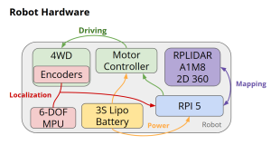
Before this week there was a black-box in my mind where the power and wiring of the robot lived, that I had to actually make concrete. I’ve never built an entire robot from scratch, so I was very careful in my approach. I started with the components we knew we needed to connect: Robot Chassis Motors, RPi 5, Lidar, IMU. From here I had much back-and-forth with ChatGPT to research and learn about the required components to connect and power each of these safely.
With some time, I established that power from our battery needed to be split into two separate streams: 5V 5A, as per the RPi 5 documentation, and 6V 10A, estimated (with plenty of buffer) based on the limited specs on the robot chassis motors. These two desired voltages informed my part search, along with economic considerations, because as a team we want to maintain room in the budget for a duplicate bot, PLUS extra wiggle room for part replacements/changes/fixes etc.
I had ChatGPT create a block diagram of how the new parts will be connected in between the core components (Robot Chassis Motors, RPi 5, Lidar, IMU), the final iteration shown below.
SWARM bot wiring diagram
After research and part finalization, I updated the team BOM to do auto total-price calculations in order to save time in the future, and logged the new parts to order.
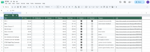
I am currently on track with the team Gantt Chart. Assuming all parts arrive next week (which they should considering it was all <2 day Amazon Prime shipping), I can stay on pace. Next weeks’ tasks are transitioning from planning/digital work to physical assembly of the chassis, drivetrain, wiring connections, and mounting of sensors. The most immediate next step is going to be creating a more detailed wiring diagram for pin connections between the Rpi, Lidar, and Motor Controller specifically based on documentation pin-outs.
Some questions left unanswered are:
Chassis encoder output voltage (not documented anywhere) is 5V or 3.3V? This determines if it is directly compatible with the Rpi 3.3V GPIO pins or not.
Motor stall and startup current quantity (not documented)? I built in buffer for these current spikes into the battery, buck converter and wire ratings, but it’s important to quantify them to make sure we won’t have any issues down the line.